Oil well Stimulation con't 1

Vertical and horizontal fractures 

Ve

Vertical fracture  occurs in deep reservoirs when  fracture gradient is less than overburden gradient
Horizontal fracture  occurs in shallow reservoirs
Fracture occurs n a direction vertical to the smallest principal stress i.e. the minimum work 


Two basic methods of hydraulic fracturing
1-Proppant fracturing
Proppant fracturing requires that small particles be pumped with the fluid into the fracture. An effort is made to pack the fracture with a bed of these particles in order to support the walls of the fracture to form a conductive path to the wellbore.
PROPPANT FRACTURING


The objective of proppant fracturing: is to pack the dynamic fracture with proppant (small particles) so that when the fracture treatment has terminated and production commences, the fracture will remain conductive. The need to pack the fracture with some form of propping agent was recognized early in the development of the process.
Production from fractured wells not propped declined rapidly.
 
One of the important design considerations will be to select a fluid capable of transporting and holding the proppant particles in suspension until the fracture has closed.

Proppant Types:
·      Sand.
·       Sintered bauxite
·       Ceramics.
1-Sand
 Sand has proven to be successful as a proppant for all types of reservoirs, and it is less expensive than other types of proppant.
Sand for use as proppant should not contain more than 5 wt% fines which, if present in excessive quantities, reduce the fracture conductivity.
Advantage:
When crushed, it breaks into smaller fragments, rather than being powdered. This particular advantage helps to maintain high fracture conductivities even when the closure stresses supported by the proppant are large
2-Sintered bauxite
A high-strength proppant (compressive strength in excess of 1 x 10⁵ kPa), which does not crush as readily as sand under high closure stresses.            
Bauxite is denser (pp - 3400-3800 kg'm3) than sand (2650 kg/m3
The fracture fluid designed to transport bauxite will have to be more    viscous and hence more expensive than a fluid that will transport sand.


3-Ceramics
Other high-strength proppants have been developed which appear to have advantages with respect to sintered bauxite: however, these are not yet widely applied.
Propped Fracture Conductivity
                FC = wf kf
Wf           is the final average fracture width
Kf            permeability of proppant-packed fracture
FC         has the dimensions of length cubed; it may be reported as darcy-fcet, darcy-inches, or even millidarcy-feet.
Fracture permeability.
Final fracture permeability is strictly a function of the diameter of the proppant particles used in the treatment. According to the Blake-Kozeny equation 


dp           is the diameter of the proppant particle
*                        is the porosity of the packed, multilayer bed of proppant particles.
The fracture permeability increases with the square of the proppant particle diameter.
Therefore, it is desirable to use large proppant particles. Actually, the size of the proppant is an optimization problem that must always be settled on economic grounds. Larger particles will require more expensive fluids to transport them. The optimum will depend on a large number of factors, all of which will be discussed later.


Fracture width.

The final fracture width is strictly related to the concentration of proppant in the fracture when it closes.
For a well-designed fracture fluid, proppant settling is minimal.
          is the average dynamic fracture width at the end of pumping


mi       is the mass of proppant per unit volume of fluid
   is the density of proppant
        
  is the mass of proppant per total volume, including both proppant and fluid.


The effect of closure stresses.
The fracture conductivity can be calculated by the multiple of wf times kf.
This calculated conductivity will exceed the field value when the closure stresses exerted by the overburden become large. In this case, the proppant will embed into the formation causing the actual fracture width to be less than that calculated and also proppant crushing may cause the effective proppant radius to be reduced, thereby reducing the permeability of the fracture.
Closure stress = PBISIP - Pwf  by maintaining the bottomhole welt flowing pressure at a high level, part of the overburden stresses can be supported by the fluid in the fracture. Generally, however, to produce the well at an economic rate, pwf   is much less than the reservoir pressure (large drawdown) and the proppant must support nearly the entire overburden.

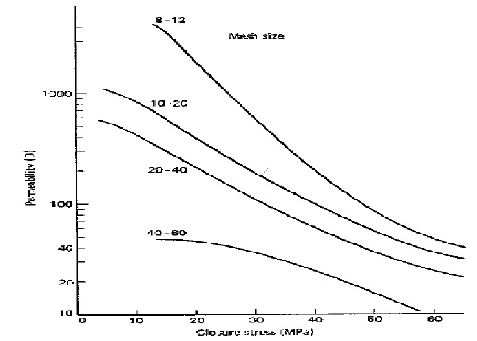
Graph showing the permeability of a propped fracture as a function of the closure stress.

Proppant Settling Velocities
The selection of a fluid is one of the critical steps in the design of a fracture treatment. One of the important properties required of the fluid is an ability to transport and hold the proppant in suspension. It is important to be able to calculate the rate at which particles settle under the influence of gravity.
Two different types of fluids will be considered here
1- Non-Newtonian polymer solutions

2- Foams

1-Non-Newtonian fluids
When a particle settles in a fluid under the influence of gravity, it reaches a constant velocity so that the frictional forces are in balance with the gravitational forces. For Reynold's numbers less than about 2, that is, for
The settling velocity (vs)
The apparent viscosity depends on shear rate and is therefore not a constant. Slattery and Bird have shown that for particles settling in a quiescent non-Newtonian fluid.


2-Foams
The settling of proppant particles in foams must be a complex function of the wettability of the particles, the quality of the foam, and its stability.
 No general theory has been presented which shows the relationship of these factors.


Design and optimization of fracture processes  
The final design will be best in some economic sense and requires different considerations:
1-Proppant fracture
   1-Selection of fracture fluid and additives
   2-Design of proppant fracturing treatments
   3-Practical considerations in designing fracture
2-Selection of fracture fluid and additives fluid properties:
   1-Low fluid loss
   2-Ability to carry and suspend the proppant
   3-Low friction loss
   4-Easy to recover from the formation
   5-Compatible with formation fluids and nondamaging
   6-Reasonable cost

Oil well Stimulation con't


Hydraulic fracturing


hydraulic fracturing
has been and will remain, one of the primary engineering tools for improving well productivity. This is achieved by
placing a conductive channel through near wellbore


damage, bypassing this crucial zone


extending the channel to a significant depth into
the reservoir to further increase productivity
placing the channel such that fluid flow in the reservoir is altered


Proper treatment design is thus tied to several disciplines
production engineering
rock mechanics
fluid mechanics
selection of optimum materials
operations.


what is fracturing


If fluid is pumped into a well faster than the fluid
can escape into the formation , inevitably pressure rises,
and at some point something breaks.


Injecting fluid into formation at pressure higher than the fracturing pressure of the formation creates fractures which propagate as more fluid is injected


Methods of hydraulic fractures
Acid fracturing
Proppant fracturing


Basic reasons for hydraulic fracturing


1- increase the rate or productivity


2- improve ultimate recovery


Fracture orientation


Fracture either horizontal or vertical
pressure behavior for fracturing formation
break down pressure: the pressure required to break the formation and initiate fracture.
Propagation pressure: the pressure required to continually enlarge the fracture.
Instantaneous shut in pressure: the pressure required to hold the fracture opened.

Idealized pressure behavior during fracturing


Oil well Stimulation

Oil well stimulation plays a vital role in production operations. With oil prices at all-time highs, it is imperative from an oil company's perspective and the consumer's perspective that as much production as possible be safely extracted from the reservior .

why do wells need oil well stimulation?
Hydraulic fracturing and acid fracturing in practically all types of formations and oil gravities, when done correctly, have been shown to increase well productivity above that projected in both new and old wells. From an economic standpoint, oil produced today is more valuable than oil produced in the future. Fracturing candidates may not necessarily "need" oil well stimulation, but the economics may show that such a treatment would pay=off.
To understand why remedial stimulation (matrix acidization) is necessary, you have to consider the conditions at work, deep down inside the reservoir...
Before the well is ever drilled, the untapped hydrocarbons sit in the uppermost portions of the reservoir (atop any present water) inside the tiny pore spaces, and in equilibrium at pressures and temperatures considerably different from surface conditions.
Once penetrated by a well, the original equilibrium condition (pressure, temperature, and chemistry) is permanently changed with the introduction of water or oil-based drilling fluids loaded with suspended clays, and the circulation of cement slurries. The interaction of the introduced fluids with those originally present within the reservoir, coupled with pressure and temperature changes can cause a variety of effects which, in turn, can plug the numerous odd-shaped pores causing formation damage. Some of the types of damage include: scale formation, clay swelling, fines migration, and organic deposition.
Petroleum engineers refer to the level of formation damage around the wellbore as skin effect. A numerical value is used to relate the level of formation damage. A positive skin factor reflects damage/impedance to normal well productivity, while a negative value reflects productivity enhancement.
Formation damage, however, is not limited to initial production operations. Remedial operations of all kinds from well killing to well stimulation itself, can cause formation damage. Nor is fines and scale generation limited to the reservoir. They can also develop in the wellbore in casing and tubulars, and be introduced from surface flowlines and incompatible injection fluids. These fines and precipitates can plug pores and pipe throughout an entire oil field.
In short, any operation throughout a well's life can cause formation damage and impede productivity.
types of  Stimulation:-
1- Hydraulic fracturing
2- Acid fracturing

Pumping applications in petroleum con't

Sucker rod pump
An artificial-lift pumping system using a surface power source to drive a downhole pump assembly. A beam and crank assembly creates reciprocating motion in a sucker-rod string that connects to the downhole pump assembly. The pump contains a plunger and valve assembly to convert the reciprocating motion to vertical fluid movement.
 
EXPLANATION OF HOW IT WORKS/ IS USED:


Figure B: Operational Detail of Sucker Rod Pump
Here the plunger is shown at its lowest position. The pitman arm and the crank are in-line. The maximum pumping angle, denoted as theta in the calculations, is shown. L is the stroke length. After one stroke, the plunger moves upward by one stroke length and the walking beam pivots. The crank also rotates counterclockwise. At the end of the upstroke the pitman arm, the crank, and the walking beam are in-line.
For name and location of parts, see Figure A.
  1. A motor supplies power to a gear box. A gearbox reduces the angular velocity and increases the torque relative to this input.
  2. As shown in Figure B, (the crank turns counterclockwise) and lifts the counterweight. Since the crank is connected to the walking beam via the pitman arm, the beam pivots and submerges the plunger. Figure B also shows the horsehead at its lowest position. This marks the end of the down stroke. Note that the crank and the pitman arm are in-line at this position.
  3. The upstroke raises the horsehead and the plunger, along with the fluid being pumped. The upstroke begins at the point shown in Figure B. At the end of the upstroke, all joints are in-line. This geometric constraint determines the length of the pitman arn.
Figures C(a) and C(b) show the plunger and ball valves in more detail. These valves are opened by fluid flow alone. On the upstroke, the riding valve is closed and the standing valve is open. Fluid above and within the plunger is lifted out of the casing while more fluid is pumped into the well. On the down stroke, the riding valve is opened and the standing valve is closed. Fluid flows into the plunger and no fluid is allowed to leave the well.


Hydraulic pump

A hydraulic ram or impulse pump is a device which uses the energy of fallingwater to lift a lesser amount of water to a higher elevation than the source.See Figure 1.  There are only two moving parts, thus there is littleto wear out.  Hydraulic rams are relatively economical to purchaseand install.  One can be built with detailed plans and if properlyinstalled, they will give many trouble-free years of service with no pumpingcosts.  For these reasons, the hydraulic ram is an attractive solutionwhere a large gravity flow exists.  A ram should be considered whenthere is a source that can provide at least seven times more water thanthe ram is to pump and the water is, or can be made, free of trash andsand.  There must be a site for the ram at least 0.5m below the watersource and water must be needed at a level higher than the source


 A Jet Pump
A Jet Pump is a type of impeller-diffuser pump that is used to draw water from wells into residences. It can be used for both shallow (25 feet or less) and deep wells (up to about 200 feet.)
Shown here is the underwater part of a deep well jet pump. Above the surface is a standard impeller-diffuser type pump. The output of the diffuser is split, and half to three-fourths of the water is sent back down the well through the Pressure Pipe (shown on the right here).
At the end of the pressure pipe the water is accelerated through a cone-shaped nozzle at the end of the pressure pipe, shown here within a red cutaway section. Then the water goes through a Venturi in the Suction Pipe (the pipe on the left).
The venturi has two parts: the Venturi Throat, which is the pinched section of the suction tube; and above that is the venturi itself which is the part where the tube widens and connects to the suction pipe.
The venturi speeds up the water causing a pressure drop which sucks in more water through the intake at the very base of the unit. The water goes up the Suction Pipe and through the impeller -- most of it for another trip around to the venturi.
Advantages
•  Increasing the speed before the onset of cavitation, because of the raised internal dynamic pressure
•  High power density (with respect to volume) of both the propulsor and the prime mover (because a smaller, higher-speed unit can be used)
•  Protection of the rotating element, making operation safer around swimmers and aquatic life
•  Improved shallow-water operations, because only the inlet needs to be submerged
•  Increased maneuverability, by adding a steerable nozzle to create vectored thrust
Disadvantages
•  Can be less efficient than a propeller at low speed
•  More expensive
•  Higher weight in the boat because of entrained water
•  Will not perform well if the boat is heavier than the jet is sized to propel
•  Can suffer more easily from cavitation than a conventional propeller


Pumping applications in petroleum


Pumping application in petroleum
Types of pumps in petroleum:-

1-ELECTRO SUBMERSIBLE OIL PUMP (esp.)

2-sucker rod pump.

3-hydraulic pump.

4- JET PUMP .

5- Progressive Cavity Pumps


ELECTRO SUBMERSIBLE OIL PUMP (esp.)

Electrosumergible pumping system (BES) is an artificial lift system that uses electrical energy converted into mechanical energy to lift a column of fluid from a given level to the surface, discharging at a given pressure. As in all cases when you want to design an artificial lift system, you should remember:
“Not always the cheapest is the most convenient”
“Not always the most expensive is the best solution”
Electrosumergible pumping has proven to be an artificial system of efficient and economical production. In the petroleum industry, compared with other artificial production systems has advantages and disadvantages, because for various reasons may not always be the best, well that is a candidate to produce artificially pumping electrosumergible must have characteristics that do not affect its operation relationships such as high gas / oil, high temperatures, the presence of sand in the produced fluids, which are factors with undesirable influences on the efficiency of the rig.
Among the features of the system are its ability to produce large amounts of fluid from different depths under a wide variety of conditions particularly well and is distinguished by the engine is directly coupled to the pump at the bottom of the well. The electric pump assembly works on a wide range of depths and volumes, their application is particularly successful when conditions are conducive to producing high volumes of liquids with low gas-oil ratio.
Description of pumping electrosumergible
A typical unit consists electrosumergible pump at the bottom of the pot for the following components: electric motor, protector, inlet section, electric submersible pumps and cable driver. The external parts are: head, cable surface. Control panel, transformer.
Key Components of a Pumping System electrosumergible:
1. Engine
2. Bomba (Stages, consisting of impeller and diffuser each)
3. Cable
4. Cable Restraint Suncho
5. Gas Separator
6. Section Sealant
7. Pressure Sensor Fund
8. Transformer (surface)
9. Variable Control
Team electrosumergible oil
Motor left) and pump (right)
Key features of a pumping system electrosumergible
It is necessary to bear in mind the conditions that tend to limit the use of this system:
1. It is not advisable to use this system in high regard GLR wells.
2. It is not advisable to use this system in wells under P. I. and low pressure.
3. It is essential for the design, knowing the bubble pressure of the reservoir will drain the well and the current pressure in the reservoir.
4. The importance of the latter is that it is not pumping a single phase (liquid) two-phase (gas + liquid), because the equation changes Productivity Index as the case, hence why it is necessary know the pressure of the reservoir and its value against its bubble pressure.
5. The mechanical conditions of the well may be another limiting factor so it is necessary to know the characteristics of the completion (diameter of the casing and the open intervals to production).
6. Another factor to consider is certainly the water cut, like most artificial lift systems, it is designed for incompressible fluids, and oil as we know it is understandable, even more so when accompanied by gas.
7. It must also consider the type of reservoir fluid and its characteristics (high viscosity of the fluid is a limiting factor, and in some cases, unconsolidated reservoirs, the fluids produced are accompanied by sand grains and in others are inlaid upon entering the facility, damaging parts)
Steps to design a pumping installation electrosumergible:
Collection of information from the well:
* Diameter, grade and weight of the liners.
* Perforated intervals.
* Estimated depth of the pump.
* Pressure: static and flowing to the midpoint of perforations.
Reservoir Data:
* Bubble Pressure
Production Data:
* Estimated Regime
*% Water
* G.L.R.
* Level Static
* Level Dynamic
Fluid Characteristics:
Oil Specific Gravity
Water Specific Gravity
Oil Viscosity
Additional considerations to take into account:
* Production of Fine
* Corrosion
* Scale
Emulsions *
* Presence of Sales
* Presence of H2S
* High Temperature
Main equations that facilitate the design of an artificial lift system by pumping electrosumergible (BES)
Productivity Index equation (when the pressure is greater than the bubble pressure, flow of a single phase):
Productivity Index equation (when the pressure is less than the bubble pressure, or two-phase flow equation Vogel)
Where:
Qmax: Maximum flow at zero pressure
PWF: Background Fluent pressure (referring to the vertical midpoint of the perforations)
Pr: Pressure from the reservoir to a given flow
q: flow regime PWF pressure
The level (height) of the fluid dynamic pump is calculated considering the pressure from the pump location (usually 100 ‘over the top of the perforations), and finally the submergence of the reservoir pressure at that depth.
The total height is the sum of the heights (pressures) represented by the frictional pressure loss in the tubing and the discharge pressure and the dynamic height, according to the following equation:
Overall height (Ht = Heat). It is the sheepdog that the pump must overcome.
Where:
Ht: Height
Hd: Height of discharge
Hs: Suction Head
Depth of Discharge. It is the algebraic sum of static discharge height and height due to friction losses in the system:
Where:
Hed: Height static discharge (pressure difference between the level of submergence and unloading, feet)
HFD: Height equivalent losses due to friction
Ps: discharge pressure in the separator (feet)
Suction Head. It is the algebraic sum of the static head plus friction losses in the suction of the pump:
Where:
Hes: Pump Vertical Depth (feet)
Hf: Height equivalent to the friction loss (0 feet)
Prs: Pressure from the reservoir to the depth of suction (ft)
To apply the equations is necessary first to determine the optimal value of q from the Vogel equation, the curve plotting the values of the regime (q) vs, dynamic height.
Once found the corresponding height value and the graph will pump performance is selected and the height and the corresponding power per stage, dividing the value of Ht between the height value found, you get the number of stages, then the latter value multiplied by the power (hp) is the total power of the engine brake.
Determination of Dynamic Level:
* Calculate the distance between the midpoint and the top of the holes (vertical)
* There is the algebraic sum of the level of submergence of the pump (1000 ‘) the pressure at the midpoint of the perforations and the distance from the pump at the same point (all in feet)
* Replaced the value found above and the other values in the equation and is the total charge flow regime selected.
to be con't