Tubulars con't lec ( 6 )

High Strength
Tubing Failure

Failures of high-strength tubing are normally caused by:
  •  Manufacturing defects
  •  Handling/transportation damage
  •  Hydrogen embrittlement

API Tubing
Connections

There are two standard API coupling tubing connections available:


The API EUE type of connection is available in 23/8”, 27/8”, 31/2” and 41/2”.

Extra Clearance

 It is occasionally necessary to provide extra clearance to enable tubing
installation. To accommodate this, API couplings can be turned down (to
specified tolerances) without loss of joint strength. Special clearance collars
are usually marked with a black ring in the center of the color band indicating
steel grade. Extra-clearance, coupling-type thread forms have been developed
for non-upset tubing which have 100% joint strength.
Integral-joint premium threads provide additional clearance and are available
in a number of configurations. Some can be turned down to provide even
greater clearance. This type of joint is more expensive and is generally used in
special situations (high-pressure or gas well application).

Premium Tubing
Connections

In addition to the standard API connections, there are a wide variety of specific
joint connections available usually referred to as premium connection. Most
premium connections use a metal-to-metal seal which requires that the mating
pin and box surfaces are forced together with sufficient stress to establish a
bearing pressure greater than the differential pressure across the connection.
The bearing pressure (Pb) is defined as the pressure exerted between the metal
surfaces created by the torque used at make-up.
Premium connections are available in a wide variety of types, weights and
materials

Connection Seals

 Round thread connections form several metal-to-metal seals between the tapered
portions of pin and box surfaces. The small void between the crest and root of
the mating threads must be filled with thread compound solids in order to
transmit adequate bearing pressure from one threaded surface to another.
Some connections (e.g., HYDRIL) have large smooth metal-to-metal
connections. The threads in this type of connection have a relatively large
clearance and do not act as seals. Threads like Armco Seal Lock have both a
sealing thread and a smooth metal scaling surface (Fig. 10). A Teflon ring is
used in some premium connections to provide a supplementary seal and provide
corrosion protection.
The stresses applied during make-up and subsequent service determine the
success of the connection seal. When compiling tubular make-up procedures
the minimum, optimum and maximum torque for each connection type must be
known.


Basic String Design
and Selection

When selecting completion components, consider the factors shown below.
This of course is in addition to the basic efficiency, safety and economic
requirements of all completions.
  •  Facilitate installation
  •  Optimize production
  •  Simplify maintenance
  •  Enable stimulation or workover
  •  Provide for contingency

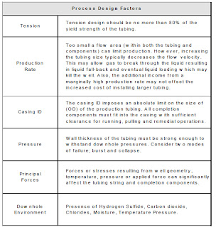
Tubular
Design Factors

The basic string design and selection process should take into
account the following guidelines before detailed planning is begun:


Drift Inspection

 Before running in the hole, drift the tubing with an API drift mandrel to ensure
the internal clearance is within tolerance.
Handle all tubing (new, used or reconditioned) with thread protectors in place.
Do not remove the thread protectors until the tubing is ready to be stabbed.
High-strength tubing is particularly susceptible to damage caused by improper
shipping and handling practices.


Measurement


 When running tubing and completion components, careful measurement of
each joint or item is essential. Each measurement is recorded in a tally book
against the joint number which should be clearly marked on each joint. The
tape used is divided into feet and decimal fractions, (e.g., the reading for 20 ft.,
6 in., would be read as 20.5 ft.).
Tubing joints (and other string components) are measured from the box end to
the beginning of the threads on the pin end (not the end). Record completion
components on a separate sheet of the tally book. The length, OD, grade and
ID are listed as appropriate for each component.
When the grade and size of pipe has been chosen, details of the following
points should be made known to field personnel:
  •  Handling - Tubing, especially high grade tubing (P-105, etc.)
must be handled carefully without dropping, denting, or nicking.
  •  Torque - Too loose or too tight make-up on a joint connection
can result in failure.
  •  Record (Tally) keeping - Accurate measuring and recording of
tubulars and placement of downhole components is essential. A
packer accidentally placed below the perforated interval is a prime
example of mis-measuring or miscounting tubing joints.

Running the
Tubing String

NOTE: Use PPE equipment.

Formulas and Calculations for Drilling, Production, and Workover Second Edition Norton J. Lapeyrouse free download


CONTENTS

PREFACE .................................................. vii
1 BASIC FORMULAS ...................................... .1
Pressure Gradient 1. Hydrostatic Pressure 3. Converting Pressure into
Mud Weight 4. Specific Gravity 5. Equivalent Circulating Density 6.
Maximum Allowable Mud Weight 7. Pump Output 7. Annular
Velocity 9. Capacity Formulas 12. Control Drilling 19. Buoyancy
Factor 20. Hydrostatic Pressure Decrease When Pulling Pipe out of
the Hole 20. Loss of Overbalance Due to Falling Mud Level 22.
Formation Temperature 24. Hydraulic Horsepower 25. Drill Pipe/Drill
Collar Calculations 25. Pump Pressure/Pump Stroke Relationship 27.
Cost per Foot 28. Temperature Conversion Formulas 29.
2 BASIC CALCULATIONS ................................. .31
Volumes and Strokes 3 1. Slug Calculations 33. Accumulator
Capacity 37. Bulk Density of Cuttings 41. Drill String Design
(Limitations) 42. Ton-Mile Calculations 44. Cementing Calculations 47.
Weighted Cement Calculations 53. Calculations for the Number of
Sacks of Cement Required 54. Calculations for the Number of Feet to
Be Cemented 57. Setting a Balanced Cement Plug 61. Differential
Hydrostatic Pressure Between Cement in the Annulus and Mud Inside
the Casing 65. Hydraulicing Casing 66. Depth of a Washout 70. Lost
Returns-Loss of Overbalance 7 1. Stuck Pipe Calculations 72.
Calculations Required for Spotting Pills 75. Pressure Required to
Break Circulation 79.
3 DRILLING FLUIDS ....................................... 81
Increase Mud Density 81. Dilution 85. Mixing Fluids of Different
Densities 86. Oil-Based Mud Calculations 87. Solids Analysis 91. Solids
Fractions 95. Dilution of Mud System 96. Displacement-Barrels of
Water/Slurry Required 97. Evaluation of Hydrocyclone 97. Evaluation
of Centrifuge 99.
4 PRESSURE CONTROL . . . . . . . . . . . . . . . . . . . . . . . . . . . . . . . . . . . .lo3
Kill Sheets and Related Calculations 103. Prerecorded
Information 115. Kick Analysis 124. Pressure Analysis 137.
Stripping/Snubbing Calculations 139. Subsea Considerations 144.
Workover Operations 153. Controlling Gas Migration 157. Gas
Lubrication 159. Annular Stripping Procedures 161.
5 ENGINEERING CALCULATIONS . . . . . . . . . . . . . . . . . . . . . . . . . .165
Bit Nozzle Selection-Optimized Hydraulics 165. Hydraulics
Analysis 169. Critical Annular Velocity and Critical Flow Rate 173.
“d” Exponent 174. Cuttings Slip Velocity 175. Surge and Swab
Pressures 179. Equivalent Circulation Density 187. Fracture Gradient
Determination-Surface Application 190. Fracture Gradient
Determination-Subsea Application 194. Directional Drilling
Calculations 197. Miscellaneous Equations and Calculations 203.
APPENDIXA .............................................. 209
APPENDIX B .............................................. 217
INDEX .................................................... 221
vi


PREFACE

Over the last several years, hundreds of oilfield personnel have told me that
they have enjoyed this book. Some use it as a secondary reference source:
others use it as their primary source for formulas and calculations; still others
use it to reduce the volume of materials they must carry to the rig floor or
job site.
Regardless of the reason people use it, the primary purpose of the book
is to provide a convenient source of reference to those people who don’t use
formulas and calculations on a regular basis.
In the preface to the first edition, I made reference to a driller who carried
a briefcase full of books with him each time he went to the rig floor. I also
mentioned a drilling supervisor who carried two briefcases of books. This
book should reduce the number of books each of them needs to perform
his job.
This book is still intended to serve oilfield workers for the entirety of their
careers. I have added several formulas and calculations, some in English field
units and some in Metric units. I have also added the Volumetric Procedure,
the Lubricate and Bleed Procedure (both Volume and Pressure Method), and
stripping procedures (both the Strip and Bleed Procedure and the Combined
Stripping and Volumetric Procedure).
This book has been designed for convenience. It will occupy very little
space in anyone’s briefcase. It has a spiral binding so it will lay flat and stay
open on a desk. The Table of Contents and the Index make looking up formulas
and calculations quick and easy. Examples are used throughout to
make the formulas as easy as possible to understand and work, and often
exact words are used rather than symbols.
This book is dedicated to the thousands of oilfield hands worldwide who
have to use formulas and calculations, whether on a daily basis or once or
twice a year, and who have problems remembering them. This book should
make their jobs a little easier.