A rig workover is defined as any operation performed on a well subsequent to the initial
completion which requires a rig. Such workovers are usually required to repair or service
the completion, to enhance the well productivity, to remove obstructions within the
wellbore or to correct a problem for safety reasons
Types of Rig Workovers
There are two main categories of rig workovers which are discussed below.
• Conventional Workovers – A conventional worker can involve
(1) removal of tubing and most of the other retrievable downhole equipment;
(2) repair or alteration of the permanent downhole well configuration;
(3) adding perforations or completionintervals
(4) the revamping of the retrievable downhole equipment to suit current and future production plans or artificial lift requirements.
• Concentric Workovers – A concentric tubing workover is one in which a small
diameter workstring is run inside the permanent tubing string. Concentric tubing
methods offer a means of minimizing workover costs whenever wireline techniques
are not feasible because of the need for fluid circulation. Savings occur as a result of
(1) reduced workover time;
(2) lower equipment costs realized by avoiding the necessity retrieving the installed well tubing (3) use of smaller workover rig
Planning
Thorough workover planning is essential to the execution of a profitable workover. The
subject of workover planning has been covered in a previous section, where we saw that
some of the principal items to be considered when planning a workover technique are :
• Well Considerations – This includes the mechanical integrity of the completion and its
past history. The characteristics of the producing zone and the nature of the fluids
involved must also be considered.
• Workover Rig Considerations – The type and size of the rig can influence the success and payout period of a proposed workover.
• Personnel – Experiences supervisors and crew can greatly improve workover
efficiency and success ratios.
• Auxiliary Tools and Services – Rental charges and support services can be a
significant portion of the workover cost. , “Workover Planning”, contains detailed information on this and other subjects pertaining to workover planning
A conventional workover is loosely defined as a workover in which the well is killed and the tubing is removed from the well. Using this definition, we see that many different rig
types can be used to perform a conventional workover, including drilling rigs, conventional
workover rigs, and snubbing units. The following section will discuss the primary rig used
for conventional workovers, which is the conventional workover rig. Figure 8 is a
schematic drawing of a conventional workover rig showing some of the items discussed
below.
1) Derrick or Mast
The mast is a telescoping arrangement which forms the final load-bearing structure of the
workover rig. The mast is telescoping for portability considerations. Typical dimensions
for the mast are an extended height of 100 ft and a maximum hook-load capacity of 230,000
lbf.
2) Drawworks
The drawworks has a revolving drum around which the drilling line is spooled. The
drawworks is operated with a clutch and a chain-and-gear drive, powered by a diesel engine
or an electric motor in the case of some drillings rigs. A main brake is used to stop the
drum and is assisted by a hydraulic or electric brake when heavy loads are being raised or
lowered.
The drilling line is a wire rope ranging from 3/4 to 1-1/2 inches in diameter. The drilling
line is strung through a series of pulleys (or sheaves) in the crown block and traveling block. One end of the drilling line is attached to the drum in the drawworks. This line is called the fast line. The other end of the drilling line, called the deadline, is anchored to the rig and does not move. A sandline is sometimes included which can be used to hoist equipment or swab the well.
kelly, and the rotary table. These items are briefly discussed below.
• Swivel – The swivel supports the weight of the workstring, provides a passageway for
fluids to enter the workstring, and permits rotation of the workstring by virtue of its
seals and bearings. In short, it is the item which permit simultaneous circulation and
rotation.
• Kelly – The kelly is a 4 or 6 sided joint of pipe which is connected to both the
workstring below and the swivel above. It fits into a kelly bushing, with a
corresponding shapangles of the kelly allow torque to be transmitted to the pipe so that it can be rotated.
• Rotary Table – The rotary table is set in the rig floor and driven (rotated) by the rig’s
engines. It imparts rotation to the workstring via the square-or hexagonal shouldered
kelly.
• Power Swivel – On some smaller rigs the rotary table–kelly arrangement is replaced
by a power swivel. The power swivel is a motor driven by pressurized hydraulic fluid.
It is lighter and more portable than the rotary table method, but it is not made for
heavy-duty milling operations such as milling up permanent packers or drilling deeper.
4) Pipe
The type and size of workstring used is dictated by the requirements of the job and the
dimensions of the production casing string or liner. In many case 2-3/8-in. EUE tubing has
been found to offer a good compromise between strength, derrick load, and ease of
handling. On occasions when extensive milling or drilling is anticipated, a string of small
diameter drill pipe such as 2-7/8-in. is often run because drill pipe connections are
shouldered connections having a much higher allowable torque rating than ordinary tubing.
5) Circulating System
The circulating system is composed of the pumps, fluid mixing tanks, fluid treating
equipment, and the standpipe and rotary hose.
• Pumps – The pumps used in conventional rig workovers are triplex plunger pumps.
Usually, two pumps are used, each having the capacity of pumping roughly 3 BPM at
a maximum pressure of 3000 psi.
• Tanks – Typically, a 150 bbl compartmented tank is used for conventional workover
operations. The tank contains mixing sections, measuring sections, and a fluid storage
section.
• Treating Equipment – Although one of the primary means of cleaning the completion fluid is to allow solids to settle out in the tanks, additional equipment such as filters, shale-shakers, desanders, or gas separators may be added, depending on the nature of
the fluid and the workover being performed.
• Standpipe/Rotary Hose - The standpipe is a vertical pipe mounted to the rig mast
which carries fluid up to the rotary hose, a flexible piece of high pressure hose
connected to the swivel. The rotary hose is required so that circulation may be
maintained while the workstring is being lowered or raised.
6) Well Control Equipment
The general types of well control equipment and their functions were given in the “WellKilling” section of this chapter.
Depth Capabilities
Conventional workovers are usually only limited in depth of operation by the strength of
the workstring and the rated hookload of the mast. This is not as simple as it may sound,
however, because it can be difficult to calculate the exact load present on the workstring
during the workover. However, one place to begin is by calculating a theoretical maximum
depth for non-tapered string. We do this by the following equation :
wt Yield strength (lbf)
X L (ft) = ft S.F.
For safety factors in the 1.5-1.8 range and N-80 grade tubulars, the maximum depth (L) is in
the range of 13,000-16,000 ft. Beyond this depth, a tapered string must be run, using heavy-walled tubing in the upper portion of the hole.


Recompletion
The kind of rig used for the recompletion depends on wellbore specifics. If the intended interval after the workover is above an existing retrievable packer then a
conventional workover rig must be used to unseat the packer, pick up the tubing, etc.
If the new completion interval is below the existing perforations, however, the option theoretically exists to recomplete using concentric techniques or a conventional rig.
The decision then is based on such factors as depth, hole angle, casing and tubing size, etc., and their effect on the ability to mill out cement a cement plug to perforate the lower zone.
Usually, a conventional workover scheme is selected.
If the new completion interval is higher than the old interval, yet still below the packer then concentric work usually becomes very attractive. In this case the old perforations can be squeezed and a cement plug left in the casing.
It is a very common practice when completing a wellbore that intersects a number of distinctly different zones to complete from the bottom up. The lowermost zone is produced
first, then it is squeezed and the next higher zone is perforated. This procedure is repeated until all the zones are depleted.

Repair/Replace Downhole Equipment
The type of workover rig that is required for repair or replacement of downhole equipment depends on what downhole equipment is involved. If the equipment is suspended in the
tubing string, then a wireline unit can be used. Examples of this type of workover are
pulling subsurface safety valves, repair of gas-lift valves, installation of tubing patches, etc.
For other repair/replacement operations, however, a conventional rig usually be required since retrieval of the entire completion string becomes necessary. Examples in this
category include repair of replacement of the packer, retrieval of the screen in a gravelpacked completion, retrieval of corroded tubing, etc.

Stimulation
Stimulation treatments are so varied that each of the general workover categories, bullhead, concentric, and conventional, can be the optimum solution. Each one of these is discussed
below.
• Bullhead – Bullhead methods are often used for injection of small volumes of chemicals such as solvents, surfactants, and small acid jobs. They work best if the treating interval is fairly short, but special fluid diversion techniques can be used to
improve coverage of longer intervals. Large hydraulic and acid fracturing treatments can also be bullheaded if the tubing is fairly large (for low friction pressure) and if the
downhole equipment, especially the packer, can withstand the forces induced by high pressure injection of a cold fluid.
• Concentric – Many matrix acid treatments are pumped through small diemeter
workstrings and coiled tubing because reciprocation of the workstring through the treating interval improves coverage of the zones by the acid. Coiled tubing is especially useful because it can be reciprocated over long lengths while maintaining
fluid injection. Scale deposits are also often removed using concentric techniques.
• Conventional – A conventional workover rig is primarily required when a well is to be fractured and the existing completion must first be pulled either because the tubing is
too small to permit high injection rates or because the packer mechanism was not designed to withstand the tensile forces generated during fracture treatments.
Clean-Out
Both conventional and concentric techniques can be used for wellbore clean-out operations.
The choice depends to a large extent on the size of the casing, the material to be washedout, and the fluids available. In general, reverse circulation is preferred because of the
higher velocities through the tubing which improve solids transport. This in general rulees out the use of coiled tubing because it has no collapse resistance. Concentric strings can
often be used, and their applicability should always be investigated since they are much cheaper than conventional rigs.
Planning A Workover
When planning a workover operation for a well, the engineer should :
· Identify the cause of the well problem.
· Determine which types of workover operations will solve the problem.
· Determine which workover techniques and equipment are available to perform the
workover.
· Evaluate the economics, advantages and limitations of alternative workover techniques.
· Select the appropriate technique for the operation.
· Implement a safe and efficient field operations.
· Analyze, record, and file the workover procedures and results.
WELL PROBLEMS REQUIRING WORKOVERS
Workover operations are performed for many reasons. Workovers may be required inproblem wells to :
· Increase a declining production or injection rate caused by low reservoir pressure, low reservoir permeability, formation damage, wellbore restrictions, high viscosity oil,
improper equipment sizing, or inadequate artificial lift.
· Reduce excessive water or gas production.
· Repair mechanical failures.
· Repair primary cementing failures.
It may also be necessary to perform a workover on a non-problem well to :
· Gain additional production by recompleting or stimulating a well.
· Evaluate the well or reservoir.
· Convert an existing well to an injection or disposal well.
Low Reservoir Pressure
In the life of a well, the producing rate will decline as reservoir pressure declines. To maintain a constant producing rate as reservoir pressure declines, the flowing bottom-hole
pressure must be reduced. The amount of pressure reduction required depends on the productivity index (PI) of the well.
For example, with a reservoir pressure of 2000 psi, withdrawal of 400 barrels of fluid per day from a well with a PI of 2 will require a flowing bottom-hole pressure of 1800 psi. If the
reservoir pressure falls to 1000 psi, however, the flowing bottom-hole pressure must now be drawn down to 800 psi to produce 400 barrels per day. This pressure may be too low to
allow the well to flow.
The reservoir drive mechanism has a direct bearing on how long reservoir pressure can provide a high flowing bottom-hole pressure. As shown in Figure 1, water, gas-cap, and
dissolved-gas-drive producing mechanisms each exhibit distinct pressure behavior as the oil in place is produced. Reservoir pressure in dissolved-gas-drive reservoirs drops rapidly and
continuously with withdrawals. Gas-cap and water-drive reservoirs are less of a problem from a pressure maintenance standpoint.
From a workover standpoint, low reservoir pressure presents a difficult situation. Stimulation is less effective than in a high-pressure reservoir because there is less pressure differential
to capitalize on the increased permeability. Perforating an additional interval is a temporary measure, at best, and may complicate future workovers. Installation of artificial lift
equipment is often the only practical approach to increased production

Low Reservoir Permeability
Once the fluids near the wellbore are produced, productivity in a reservoir of low natural permeability declines rapidly. Wells completed in very low permeability formations are
usually stimulated to increase reservoir permeability away from the near-wellbore region.
Unless formation damage is also present, matrix acidizing is not applicable in this type of stimulation. A large-volume hydraulic fracturing treatment, designed to yield high conductivity and maximum drainage area, is usually the most effective approach.

Excessive Gas Production
Gas production form an oil well result from a gas originally dissolved in the reservoir oil or from free gas that has segregated and become trapped above the oil as a gas cap. Free gas
may also enter the wellbore from a gas zone separate from the oil reservoir through channels in the primary cement or as a result of casing leaks.
· Solution Gas –
In the dissolved-gas-drive reservoir, gas originally in the oil is liberated from solution as oil production begins and reservoir pressure declines. Further liberation and expansion of solution gas is requirement for primary oil recovery from a reservoir
of this type. As oil withdrawals continue, the increase in gas saturation permits gas to be produced along with the oil. As production proceeds, the relative permeability of the
rock to oil diminishes rapidly, and gas becomes the predominant mobile fluid. High-ratio
gas production in this instance is usually not a well problem but a problem of the reservoir as a whole. Workovers are not generally successful at reducing the gas-oilratio for these wells.
Mechanical Failures
Mechanical failures requiring workovers include :
· Casing leaks –
Casing leaks result in both influx of undesirable gas or water into the wellbore and the uncontrolled loss of reservoir fluids to other zones. Since casing leaks are usually associated with corrosion, the permeability of their development increases
with lengthening well life.
· Tubing collapse –
Collapse of tubulars may result in stuck tools down-hole, as well as leaks and subsequent influx of undesirable fluids into the wellbore.
· Surface and downhole equipment failures –
Mechanical failures are often associated with installed well equipment such as tubing, packers, and artificial-lift. The
first indication of this type of failure is often an observation of unexpected pressures atthe surface.
When performing a workover to repair a mechanical failure, the engineer should study the well files to determine if other problems exist, which can be repaired at the same time.
Primary Cement Failures
A poor primary cement job resulting in channels between the formation and the casing can lead to :
· Unwanted fluid production from water or gas in the zone of interest.
· Unwanted production of water or gas from an adjacent zone.
· Collapsed casing during operations in which high pressures are applied through theperforations below a packer (squeeze cementing, hydraulic fracturing).
Conventional Workover Techniques
Conventional workover techniques are performed with a heavy-duty rig. In some cases, a
drilling rig may be used. For conventional workovers, the christmas tree is removed, and the
production tubing and down-hole equipment are removed from the well.
The main advantage of using a conventional workover rather than one of the other
techniques is flexibility. The main disadvantage is cost.
Conventional workovers can be used to perform any of the operations performed by the
other techniques described above. However, some operations can only be performed by a
conventional rig. These include tubing repair or replacement, down-hole tool repair or
replacement (unless the tool can be run or retrieved on wireline), production casing repair
above a packer, recompletion to a higher zone above a packer, and side track drilling.
Auxiliary Equipment
A detailed cost survey will usually reveal that auxiliary rig tools and equipment cost approximately as much as the rental rate of the basic workover rig. Thus, as much attention should be given to the choice of auxiliary equipment as is given to the choice of workover technique and rig rate.
Contractors vary widely with respect to the tools and equipment furnished with the rig. An inventory of the equipment provided with a rig will make comparisons of hourly rig rates more meaningful. In addition, use of an inventory will ensure that all necessary equipment is on-hand and extra equipment is not ordered.
Some of the more commonly used auxiliary equipment include :
· Workstrings and Handling Tools –
These are high-cost items. If in poor condition,
they can be responsible for many failures and delays because of fishing or wellproblems.
· Blowout Preventers –
Contractors usually furnish some type of blowout preventer.
However, the equipment provided may not be rate to handle a potential problem on the well to be reworked. In addition, the age and testing history of these preventers should
be established to ensure that the preventers are adequate to handle any hazardous situations which might occur during the workover.
· Swab Line –
Some rigs include a swab line, which can reduce the cost of completion operations, if the rig is intentionally kept in place until the zone is evaluated. However, using a rig-provided swab line can be a disadvantage if using it means that the rig is
kept in place at workover-rig rates when it could be replaced by a lower-cost swabbing unit. In addition, keep in mind that swabbing is a specialized operation. The workover
rig supervisor may not have expertise in swabbing operations comparable to that of a regular swabbing unit operator.
· Circulation Pumps –
Use of the rig pumps for workover operations can eliminate the
cost of units rented from service companies. However, in some cases, the rig pumps may not have sufficient capacity and pressure rating to perform the necessaryoperations.
· Tankage –
Workover rigs sometimes include tankage. The amount of tankage needed depends on the quantity of circulating and treating fluids needed for workover operations. The quantity of fluid which must be premixed and on-hand for well control
must also be considered.
· Air Slips and Tongs –
Use of air slips, air tongs and speed equipment allows rig
crews to operate for longer periods of time without fatigue. Proper utilization of this equipment can double the speed of tripping operations and thus save rig time.
· Electrical Equipment –
Good lighting and generator equipment is fundamental if night
operations are to be conducted.
Other Considerations
Other factors which should be considered when selecting workover techniques andequipment include safety, personnel and contingency planning.
· Safety –
In any operation, safety of the personnel is the most important factor. Every employee has the responsibility to properly use equipment, to maintain it in good condition, to observe the established working rules at all times, and to practice the
principles taught in safety training.
In addition, company personnel at the rig site should be sure that the rig and service company personnel are aware of and observe the established safety rules. This can be facilitated by holding pre-job meetings to inform all on-site personnel of safety hazards, safety equipment location and use, and established safety rules.
· Personnel –
Rigs are often chosen on the strength and capability of the equipment. In practice, personnel and supervision on a particular rig are often of equal importance to the equipment brought to the rig site. The number of men in the rig crew often dictates
the efficiency of operations. The quality of contractor supervision is extremely important on a workover rig.
The relief schedule of a contractor is also important. Contractors who work men for longer periods of time without providing relief penalize the operator with lower efficiency during the latter part of the tour of duty.
Associated with this concept are the employment practices of a contractor during slack periods. Some contractors maintain key supervisors on a full-time basis but pay rig crews only when work is available. This can result in rig crews with low experience levels.
· Contingency Planning –
Although extra, non-used equipment on-site may represent
additional cost to the workover operation, enough back-up equipment should be on hand to plan for contingencies. When planning the workover, consider what could go wrong
with the operations and plan accordingly. Pre-planning and availability of critical backup equipment can save time and money in the long run.
EVALUATING AND SELECTING A TECHNIQUE
After assessing the problem and reviewing alternative techniques, the engineer should evaluate the best alternative techniques with respect to economics, limitations and
capabilities of the technique, and other factors such as safety, expedience, and reliability.
Often, the least expensive workover is not the best workover when factors other than cost are considered.
Economic Analysis
When evaluating the economics of a single proposal or comparing economics of competitive proposal, the following questions should be considered :
· Cost –
What is the relative cost of alternative workover techniques, including rig time, auxiliary equipment rentals, and support services.
· Current Income –
What will be the effect of performing the proposed workover, or possible alternative workovers, on current income?
· Increased Recovery –
Is the well needed for optimum ultimate recovery in the
present completion interval or in possible new completion intervals? If well stimulation is contemplated, would successful stimulation increase recovery?
· Payout –
What is the direct payout, i.e., the length of time required for the total cash outlay to be recovered through the new cash inflow generated by the project?
· Rate of Return
– How much additional income is expected to result from the
workover after the payout period? How soon can this be realized?
· Loss in Deferring Workover
– If the workover is postponed, what would the cost be? Would impending additional recovery programs render workover of this well more attractive in the future?
· Risk –
What is the risk factor? The degree of risk should be weighed against anticipated gain from a successful job. The degree of risk should be assessed through past experiences in areas with similar type of work or in the same or comparable
reservoirs and wells, plus individual judgement based on available data concerning thewell and reservoir.
Capabilities/Limitations
As discussed earlier in this Chapter (Subject 19.4), the choice of workover technique is sometimes limited by the capabilities and limitations of the workover rig units. For example, treatment operations, such as remedial cementing, matrix acidizing, and corrosion treatments, sometimes require that the treatment fluid selectively placed into a single zone or portion of a zone. While wireline and concentric techniques have some flexibility in this respect, use of a conventional workover rig allows use of the full casing ID and thus a wider range of downhole tools and packers can be used. On offshore locations, the compactness of wireline and concentric units is a premium. In addition, wireline units are the quickest and most efficient, thus reducing rig time, a major
expense on offshore locations.
Conventional rigs are slow and cumbersome; however, they are not as limited by factors such as operating depth, high bottom-hole temperatures and pressures, and severe I d restrictions. All of these factors must be considered before selecting a particular workover technique to perform the desired workover operation
completion which requires a rig. Such workovers are usually required to repair or service
the completion, to enhance the well productivity, to remove obstructions within the
wellbore or to correct a problem for safety reasons
There are two main categories of rig workovers which are discussed below.
• Conventional Workovers – A conventional worker can involve
(1) removal of tubing and most of the other retrievable downhole equipment;
(2) repair or alteration of the permanent downhole well configuration;
(3) adding perforations or completionintervals
(4) the revamping of the retrievable downhole equipment to suit current and future production plans or artificial lift requirements.
• Concentric Workovers – A concentric tubing workover is one in which a small
diameter workstring is run inside the permanent tubing string. Concentric tubing
methods offer a means of minimizing workover costs whenever wireline techniques
are not feasible because of the need for fluid circulation. Savings occur as a result of
(1) reduced workover time;
(2) lower equipment costs realized by avoiding the necessity retrieving the installed well tubing (3) use of smaller workover rig
Planning
Thorough workover planning is essential to the execution of a profitable workover. The
subject of workover planning has been covered in a previous section, where we saw that
some of the principal items to be considered when planning a workover technique are :
• Well Considerations – This includes the mechanical integrity of the completion and its
past history. The characteristics of the producing zone and the nature of the fluids
involved must also be considered.
• Workover Rig Considerations – The type and size of the rig can influence the success and payout period of a proposed workover.
• Personnel – Experiences supervisors and crew can greatly improve workover
efficiency and success ratios.
• Auxiliary Tools and Services – Rental charges and support services can be a
significant portion of the workover cost. , “Workover Planning”, contains detailed information on this and other subjects pertaining to workover planning
A conventional workover is loosely defined as a workover in which the well is killed and the tubing is removed from the well. Using this definition, we see that many different rig
types can be used to perform a conventional workover, including drilling rigs, conventional
workover rigs, and snubbing units. The following section will discuss the primary rig used
for conventional workovers, which is the conventional workover rig. Figure 8 is a
schematic drawing of a conventional workover rig showing some of the items discussed
below.
1) Derrick or Mast
The mast is a telescoping arrangement which forms the final load-bearing structure of the
workover rig. The mast is telescoping for portability considerations. Typical dimensions
for the mast are an extended height of 100 ft and a maximum hook-load capacity of 230,000
lbf.
2) Drawworks
The drawworks has a revolving drum around which the drilling line is spooled. The
drawworks is operated with a clutch and a chain-and-gear drive, powered by a diesel engine
or an electric motor in the case of some drillings rigs. A main brake is used to stop the
drum and is assisted by a hydraulic or electric brake when heavy loads are being raised or
lowered.
The drilling line is a wire rope ranging from 3/4 to 1-1/2 inches in diameter. The drilling
line is strung through a series of pulleys (or sheaves) in the crown block and traveling block. One end of the drilling line is attached to the drum in the drawworks. This line is called the fast line. The other end of the drilling line, called the deadline, is anchored to the rig and does not move. A sandline is sometimes included which can be used to hoist equipment or swab the well.
3)Rotating Equipment
On most conventional workover rigs the rotating equipment consists of the swivel, thekelly, and the rotary table. These items are briefly discussed below.
• Swivel – The swivel supports the weight of the workstring, provides a passageway for
fluids to enter the workstring, and permits rotation of the workstring by virtue of its
seals and bearings. In short, it is the item which permit simultaneous circulation and
rotation.
• Kelly – The kelly is a 4 or 6 sided joint of pipe which is connected to both the
workstring below and the swivel above. It fits into a kelly bushing, with a
corresponding shapangles of the kelly allow torque to be transmitted to the pipe so that it can be rotated.
• Rotary Table – The rotary table is set in the rig floor and driven (rotated) by the rig’s
engines. It imparts rotation to the workstring via the square-or hexagonal shouldered
kelly.
• Power Swivel – On some smaller rigs the rotary table–kelly arrangement is replaced
by a power swivel. The power swivel is a motor driven by pressurized hydraulic fluid.
It is lighter and more portable than the rotary table method, but it is not made for
heavy-duty milling operations such as milling up permanent packers or drilling deeper.
4) Pipe
The type and size of workstring used is dictated by the requirements of the job and the
dimensions of the production casing string or liner. In many case 2-3/8-in. EUE tubing has
been found to offer a good compromise between strength, derrick load, and ease of
handling. On occasions when extensive milling or drilling is anticipated, a string of small
diameter drill pipe such as 2-7/8-in. is often run because drill pipe connections are
shouldered connections having a much higher allowable torque rating than ordinary tubing.
5) Circulating System
The circulating system is composed of the pumps, fluid mixing tanks, fluid treating
equipment, and the standpipe and rotary hose.
• Pumps – The pumps used in conventional rig workovers are triplex plunger pumps.
Usually, two pumps are used, each having the capacity of pumping roughly 3 BPM at
a maximum pressure of 3000 psi.
• Tanks – Typically, a 150 bbl compartmented tank is used for conventional workover
operations. The tank contains mixing sections, measuring sections, and a fluid storage
section.
• Treating Equipment – Although one of the primary means of cleaning the completion fluid is to allow solids to settle out in the tanks, additional equipment such as filters, shale-shakers, desanders, or gas separators may be added, depending on the nature of
the fluid and the workover being performed.
• Standpipe/Rotary Hose - The standpipe is a vertical pipe mounted to the rig mast
which carries fluid up to the rotary hose, a flexible piece of high pressure hose
connected to the swivel. The rotary hose is required so that circulation may be
maintained while the workstring is being lowered or raised.
6) Well Control Equipment
The general types of well control equipment and their functions were given in the “WellKilling” section of this chapter.
Depth Capabilities
Conventional workovers are usually only limited in depth of operation by the strength of
the workstring and the rated hookload of the mast. This is not as simple as it may sound,
however, because it can be difficult to calculate the exact load present on the workstring
during the workover. However, one place to begin is by calculating a theoretical maximum
depth for non-tapered string. We do this by the following equation :
wt Yield strength (lbf)
X L (ft) = ft S.F.
For safety factors in the 1.5-1.8 range and N-80 grade tubulars, the maximum depth (L) is in
the range of 13,000-16,000 ft. Beyond this depth, a tapered string must be run, using heavy-walled tubing in the upper portion of the hole.
CONCENTRIC WORKOVERS

As stated previously, a concentric workover is one in which a small diameter workstring is
run concentrically through the production tubing. this saves considerable time and the well need not be dead,
• costs associated with pulling the existing completion are by-passed,
• concentric workover rigs are generally smaller and cheaper than conventional
workover rigs.
There are very few workover or servicing needs that are not now accomplished with
concentric tubing units in most areas of PSCB operations. In fact, concentric tubing
practices are the only means of servicing tubingless/monobore completions. The
experience and confidence gained from utilizing small-diameter tubing in tubingless
completions has influenced the expanding and frequent use of concentric tubing workovers
in conventional wells.
Concentric tubing techniques are particularly popular in expensive offshore and parallelstring
conventional wells. Other advantageous applications include those wells in which it
is difficult or inadvisable to move a packer, such as when gelled mud is in the casing-tubing
annulus and when packers have been installed to isolate casing leaks or squeezed
perforations.
1) Hoisting Equipment
The hoisting system on a concentric workover rig consists of the derrick, drawworks, and
drilling line (Figure 9). The hoisting system is used for running pipe into or pulling pipe
out of the well. Depending on the size of the rig, the hoisting system may handle one, two,
or three pipe joints at a time.
Derrick – Concentric rigs have either pole masts or structural mast derricks. Hook load
capacities range from 50k pounds for the smallest rigs to about 150k pounds for larger,
skid-mounted offshore concentric rigs.
Drawworks – The drawworks consist of a revolving drum around which the drilling line or work line is spooled or wrapped. It also includes a shaft on which the catheads are mounted
(small spools to which other hoisting lines may be wrapped), along with several other
shafts, clutches, and chain-and-gear drives for speed and direction changes. It also contains
a main brake, which has the ability to stop the drum from turning. When heavy loads are
being raised or lowered, the main brake is assisted by an auxiliary hydraulic or electric
brake, which helps absorb the momentum created by a heavy load.
The drawworks for a concentric rig are driven by a diesel engine with ratings normally
ranging from1 150 to 250 horsepower.
The drilling line is made of wire rope that generally ranges from 3/4 to 1 inch in diameter.
2)Rotating Equipment
The most popular and satisfactory means of pipe rotation is a hydraulically operated power
swivel. Other methods of pipe rotation include a kelly and power tongs equipped with kelly
jaws, and a kelly and small hydraulically operated rotary table.
3)Work String
Small diameter (“macaroni”) tubing strings of various diameters and with many different
types of joints are applicable to concentric work. The choice of work string will depend on
such considerations as necessary clearance, required tensile strength and torque limits,
desired hydraulics, frequency of use, retirement and salvage aspects, and availability.
4)Circulating System
Pumping System – Because of the relatively high friction losses and small fluid volumes
encountered, concentric tubing workover rigs require high-pressure, fairly low-volume
pumps. The Gardner-Denver PE-5 triplex plunger pump is an excellent selection for this
type of service and is standard rig equipment in many areas. This particular pump is
capable of discharging about 1/2 bbl/min at 5,000 psi and 2 bbl/min at 3,000 psi. By
contrast, maximum pressure obtainable with a conventional mud pump approximates 2,000
psi. the higher pressure rating of the Gardner-Denver pump has many economic advantages
over the mud pump :
• It can be used to kill wells, thus avoiding a pump truck charge for well killing.
• It can be equipped to perform the small-volume, low pressure squeeze cementing
normally associated with concentric tubing operations.
• It can also be utilized for general oil field pumping applications.
Pumping Pressures – Table III presents examples of the pressures required to circulate salt
water through macaroni strings and back up the annulus in 2-7/8-in. casing
Well Control
Workover operations with concentric pipe are conducted through the Christmas tree, which
simplifies rig-up and rig-down procedures. A twin-ram, manually operated preventer
containing two sets of manually operated pipe rams is generally sufficient for anticipated
surface pressures of less than 3,000 psi. For pressures above 3,000 psi, a hydraulic
actuating unit should be connected to the upper ram. When necessary, a stripper-type
preventer operated by hydraulic pressure can be included. Reverse circulation is possible
with either version, but stripping is not recommended with the twin-ram type. Figure 12
illustrates the composite blowout preventer assembly. Blank rams are not required in
concentric tubing work because the Christmas tree master valve serves in this capacity
COILED TUBING WORKOVERS
Coiled tubing units (CTU) hav ebeen used for numerous types of well operations. They are
most commonly used for well clean-out, washing sand, acidizing, well kickoff, and sand
consolidation treatments. For the most part, coiled tubing techniques are not suited to
heavy-duty service because of the tensile capacity of the tubing, the hoisting capacity of the
rig, and the inability to rotate the tubing.
1)Surface Equipment
In operation, the coiled tubing is fed from the reel to the injector head and then pushed
down through the tree-mounted, hydraulically-operated BOP stack (Figure 13). The tubing
is run into and pulled from the well at speeds of up to 120 feet per minute by means of a
continuous chain-driven, traction-operated tubing injector which is driven by two hydraulic
motors. The tubing is gripped on each side by a series of contoured metal blocks in the
endless chain mechanism while the injector head exerts a pushing or pulling force of up to
about 12,000 pounds. In this manner, the tubing is run in and out of the hole under
pressure, without killing the well. Adjustable, grooved sheaves guide and straighten the
tubing as it leaves the reel and approaches the injector head. The inner end of the tubing is
connected to a rotary joint in the hub of the reel so that fluids or gas can be pumped through
the tubing as it is being run into or out of the well. CTU’s should circulate fluids
continuously while running in the hole to avoid sticking or collapsing the pipe. A level
wind mechanism similar to that on a fishing reel guides the pipe for spooling on the storage
reel.
2) Pipe
The pipe use in coiled tubing operations is a single welded string – no threaded connections
are used. Typical sizes are 3/4, 1, 1-1/4-in. In addition, both light (thin-walled) and heavy
(thick-walled) and heavy pipe are available. Yield strengths of the steel used in the tubing
vary from 60,000-80,000 psi.

3)Rotating Equipment
Pipe rotation is not possible with coiled tubing since part of the pipe is always wrapped
around the spool. Nonetheless, it is possible to rotate a bottomhole assembly using fluid
circulation down the tubing and a positive displacement motor. Another device which is
sometimes used is a rotating jet sub, which can be used to radially divert acid during a
matrix stimulation treatment. These devices are not widely used.
4) Circulating System
Circulation equipment is basically the same as for concentric workovers.
5) BOP Equipment
A blowout preventer stack for coiled tubing units is shown in Figure 14. This configuration
will allow the tubing to be packed off, supported, cut, and isolated from the rest of the
tubing on the reel should a leak at the surface occur. The BOP side outlet gives access to
the production tubing for pumping or bleeding operations.
Figure 14. Coiled Tubing Unit BOP
6) Depth
Depth Capabilities
Coiled tubing units are capable of working to 15,000-18,000 ft depending on the size of
tubing and the amount of normal and heavy wall tubing that is run. Normal tubing is
usually good to about 12,000 ft, after which heavy-wall is welded to the normal tubing to
achieve greater depth capabilities. It is considered prudent practice to leave at least 400 ft
of tubing on the spool at all times.
Pressure Considerations
There are certain special pressure considerations which need to be considered when
planning for a coiled tubing unit workover. These are discussed below.
• The wellhead pressure limitation for coiled tubing units is 5,000 psi, but many
operators restrict their use to 3,000 psi maximum.
• Reverse circulation is not permitted because thin-walled tubing is very susceptible to
collapse. As forward circulation is the only mode available, it becomes imperative to
take all necessary precautions to minimize the chance of sticking the tubing due to
solids accumulating in the annular space between the coiled tubing and the production
tubing.
• Pumping pressures can be quite large even for work at shallow depths because the
fluid must pass through the entire length of tubing on the reel, often as much as 16,000
ft. For this reason circulation rates are usually held to a maximum of a few barrels per
minute.
SNUBBING UNIT WORKOVERS
Snubbing is the procedure whereby pipe is inserted or withdrawn from a well under
pressure. There are three essential elements to the snubbing process:
• A means to force the pipe through a sealing element at a controlled upward or
downward rate.
• An effective sliding-type sealing element around the exterior of the pipe
• A means for plugging the inside of the pipe
These three elements of snubbing unit workovers are discussed below.
Advantages
For workovers, several advantages are offered by the use of hydraulic snubbing equipment
rather than conventional equipment.
• The work can be done under pressure and, in some cases, while the well is producing.
This means that formation damage due to well killing operations is eliminated.
• The well can be placed back on production quickly because cleanup time is less.
• Hydraulic workover equipment is more portable than conventional equipment and can be set up and torn down easily. This aspect is important in offshore or other remote locations where transportation of heavy equipment is difficult.
• Hydraulic workover equipment is flexible. Lifting capacities can be made high and currently range to 340,000 pounds. It is possible to handle, pull, and run large OD downhole tools of moderate length under pressure. Rotary capabilities have been
incorporated that enable the units to perform light drilling and milling work.
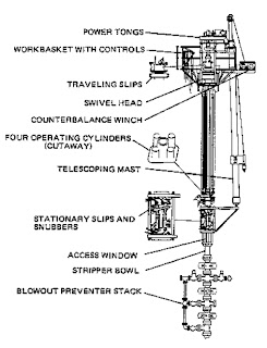
Surface Equipment
Figure 15 shows a typical hydraulic workover rig on a land location. BOP rams are visible below the vertical hydraulic cylinders. Above the cylinders is a work platform on which is
located the operating control console. The hydraulic oil supply tank, pumps, and engine driver are at ground level. Numerous hydraulic hoses connect the assemblage.
The pipe-handling assembly consists of travelling slips, stationary slips, and hydraulic cylinders . The hydraulically-powered slips are used to grip the workstring as it
is pushed into or pulled out of the well. In a snubbing operation where pipe is pushed into the well under pressure, the travelling slips grasp a joint of pipe, and are driven downward
by means of the hydraulic cylinders, forcing the workstring into the well.
At that point, the stationary slips are closed, holding the pipe in place. The travelling slips are released and lifted to their original position, then closed. When the travelling slips have
grasped the joint of pipe once again, the stationary slips are opened. This cycle is repeated
This snubbing action is powered by a set of four hydraulic cylinders. These cylinders utilize pressure supplied by hydraulic pumps to drive the pistons housed within each of the
four cylinders.
The size of the piston in each hydraulic cylinder determines the units’s push and pull capabilities.
Pipe rotation is not possible with coiled tubing since part of the pipe is always wrapped
around the spool. Nonetheless, it is possible to rotate a bottomhole assembly using fluid
circulation down the tubing and a positive displacement motor. Another device which is
sometimes used is a rotating jet sub, which can be used to radially divert acid during a
matrix stimulation treatment. These devices are not widely used.
4) Circulating System
Circulation equipment is basically the same as for concentric workovers.
5) BOP Equipment
A blowout preventer stack for coiled tubing units is shown in Figure 14. This configuration
will allow the tubing to be packed off, supported, cut, and isolated from the rest of the
tubing on the reel should a leak at the surface occur. The BOP side outlet gives access to
the production tubing for pumping or bleeding operations.
Figure 14. Coiled Tubing Unit BOP
6) Depth
Depth Capabilities
Coiled tubing units are capable of working to 15,000-18,000 ft depending on the size of
tubing and the amount of normal and heavy wall tubing that is run. Normal tubing is
usually good to about 12,000 ft, after which heavy-wall is welded to the normal tubing to
achieve greater depth capabilities. It is considered prudent practice to leave at least 400 ft
of tubing on the spool at all times.
Pressure Considerations
There are certain special pressure considerations which need to be considered when
planning for a coiled tubing unit workover. These are discussed below.
• The wellhead pressure limitation for coiled tubing units is 5,000 psi, but many
operators restrict their use to 3,000 psi maximum.
• Reverse circulation is not permitted because thin-walled tubing is very susceptible to
collapse. As forward circulation is the only mode available, it becomes imperative to
take all necessary precautions to minimize the chance of sticking the tubing due to
solids accumulating in the annular space between the coiled tubing and the production
tubing.
• Pumping pressures can be quite large even for work at shallow depths because the
fluid must pass through the entire length of tubing on the reel, often as much as 16,000
ft. For this reason circulation rates are usually held to a maximum of a few barrels per
minute.
SNUBBING UNIT WORKOVERS
Snubbing is the procedure whereby pipe is inserted or withdrawn from a well under
pressure. There are three essential elements to the snubbing process:
• A means to force the pipe through a sealing element at a controlled upward or
downward rate.
• An effective sliding-type sealing element around the exterior of the pipe
• A means for plugging the inside of the pipe
These three elements of snubbing unit workovers are discussed below.
Advantages
For workovers, several advantages are offered by the use of hydraulic snubbing equipment
rather than conventional equipment.
• The work can be done under pressure and, in some cases, while the well is producing.
This means that formation damage due to well killing operations is eliminated.
• The well can be placed back on production quickly because cleanup time is less.
• Hydraulic workover equipment is more portable than conventional equipment and can be set up and torn down easily. This aspect is important in offshore or other remote locations where transportation of heavy equipment is difficult.
• Hydraulic workover equipment is flexible. Lifting capacities can be made high and currently range to 340,000 pounds. It is possible to handle, pull, and run large OD downhole tools of moderate length under pressure. Rotary capabilities have been
incorporated that enable the units to perform light drilling and milling work.
Surface Equipment
Figure 15 shows a typical hydraulic workover rig on a land location. BOP rams are visible below the vertical hydraulic cylinders. Above the cylinders is a work platform on which is
located the operating control console. The hydraulic oil supply tank, pumps, and engine driver are at ground level. Numerous hydraulic hoses connect the assemblage.
The pipe-handling assembly consists of travelling slips, stationary slips, and hydraulic cylinders . The hydraulically-powered slips are used to grip the workstring as it
is pushed into or pulled out of the well. In a snubbing operation where pipe is pushed into the well under pressure, the travelling slips grasp a joint of pipe, and are driven downward
by means of the hydraulic cylinders, forcing the workstring into the well.
At that point, the stationary slips are closed, holding the pipe in place. The travelling slips are released and lifted to their original position, then closed. When the travelling slips have
grasped the joint of pipe once again, the stationary slips are opened. This cycle is repeated
This snubbing action is powered by a set of four hydraulic cylinders. These cylinders utilize pressure supplied by hydraulic pumps to drive the pistons housed within each of the
four cylinders.
The size of the piston in each hydraulic cylinder determines the units’s push and pull capabilities.

Pipe
Pipe sizes from 1-in. OD to 7-in. OD can be handled with hydraulic equipment, with lifts
ranging up to 340,000 capacity. The capability for handling larger sizes of pipe makes feasible the retrieval or insertion of well tubing under pressure in addition to concentric
tubing work. This capability is the most recent extension of the hydraulic workover technique. As such, the scope of potential applicability is significantly broadened in both initial completion and workover activities.
Circulating System
The circulating system (pumps, tanks, lines, etc.) is the same as for other workovers with the exception of a one-way check valve installed in the bottom of the workstring or tubing.
This check valve allows fluid to flow down from above but will not let fluid up from below.
This allows tubing to be inserted under pressure without fluid exiting the string.
Well Control System
Two basic devices are used for sealing the outside diameter of the tubing during work under pressure. These are ram-type blowout preventers and solid rubber element tubing strippers.
Stripper elements are generally considered adequate for control of pressure up to 2,500 – 3,000 psi. These elements are constructed of solid synthetic rubber compounds.
They can stretch as couplings pass so that some downhole tolls can be stripped through them. The useful life of the stripper element depends largely on the external condition of
the tubing, and will range from 10,000 to 20,000 linear feet at pressures of 3,000 psi or less.
With three BOP elements in a stack, and with piping to create an equalizing chamber, higher pressure operations are feasible. shows the sequence of operations when entering the hole using the ram BOP stack. The stack operation is summarized below
• With the top rams open and the lower rams closed on the pipe, the joint can be lowered.
• After the connection passes the top rams, the top rams close and chamber pressure equalizes with casing pressure before the lower rams open.
• High pressure thus admitted to the chamber between the two rams is held by the top rams as the joint is again lowered.
• After the connection passes the lower rams, the lower rams are closed and pressure is then released for the equalizing chamber between the rams through a vent line.
• The top rams are then opened and the cycle is repeated.
• The third set of pipe rams is located below the two working sets and is for basic well control. They serve as safety devices by not being subjected to wear in the snubbing process.
One can easily see that many maneuvers are required of an operator in stripping tubing with the use of working-ram-type preventers. In contrast, the simple stripper requires no action
to operate.
A stripper is also more economical to use than working rams. Working rams arenevertheless useful in many circumstances, and should be included in the BOP stack to
facilitate running downhole tools in order to accommodate the higher pressures sometimes encountered.
Clearly, the well pressure acting on the cross-sectional area of the plugged pipe will be lifting it upward while gravitational pull on the pipe mass will be acting downward.
Auxiliary Equipment
In some case, power tongs are used to make up or break out pipe, and are powered by air or hydraulic pressure. When circulating through the workstring or rotating the pipe, power
swivels or power subs are normally made up onto the top joint of pipe. In some cases, a hydraulically powered rotary table is mounted on top of the travelling slip assembly. The
controls for all the unit’s functions are located in the detachable workbasket, which is mounted at the top of the hydraulic cylinders.
FISHING OPERATIONS
Almost every fishing job presents special problems requiring proper analysis, creative thinking, and the exercise of good judgment to successfully accomplish the objective.
Often fishing jobs require many tools and frequent trips with the work string, which consume much rig time and can result in a high-cost operation
Reasons For Fishing
Tools and equipment are lost in the hole for variety of reasons. A very common example is seen during drilling operations, when part of the drill string may get stuck in the hole. In
workover operations, common causes of fishing are wireline tools which are left in the hole,
screens and slotted liners used in gravel-packed completions which need to be retrieved, stuck packers, parted workstring, and tools which inadvertently fall into the wellbore
(wrenches, slip dies, etc.). Each of these different types of “fish” require special tools and techniques for retrieval.
Planning
The costs and inherent risks when fishing make it imperative that the operations and engineering personnel involved communicate freely. Predicted additional cost and risk in
certain types of fishing operations may make it necessary to change the whole job plan and objective.
Factors that must be considered in planning a fishing job are :
• Mechanical condition of the wellbore tubulars and the fluids or solids that they contain
• Knowledge of the size, amount, and type of fish (all dimensions are important)
• Location of fish
• Tools and method to be used for recovery
• Predicted cost, probability of success, and risks of failure
For relatively simple, straight forward fishing jobs such as the recovery of pipe inadvertently dropped or left in the hole, an overshot can be used for fast, inexpensive recovery. For a more complicated job-such as recovery of stuck, cemented, or plasticized pipe, ore recovery of several wireline tools with wireline on top of them – special fishing tools and skills will be required. When cases such as these arise, an experienced fishingtool operator should be used.
There are many types of fishing tools which can be grouped into categories according to
how they are used.
• Catching or retrieving tools
• Washover tools
• Cutting tools
• Milling tools

WORKOVER RIG SELECTION
The final part of this section deals with workover rig selection criteria. Typical workover operations are listed as keywords in the left-hand margin, and the different factors affecting
rig selection for that particular operation are discussed.
1) Drilling and Milling
Most major drilling and milling operations are conducted with conventional workover rigs.
Such operations include milling up packers, drilling cement, sidetracking, deepening, etc.
conventional rigs are preferred for a number of reasons. For drilling it is often necessary to use a high weight-on-bit in order to achieve reasonable penetration rates. This requires a
larger workstring. High torque requirements are another reason for using larger tubular goods. In many cases where drilling is required, a new downhole completion configuration
will be required, which requires a conventional rig anyway.
Concentric rigs are suitable for some light milling operations, however. In particular, they can be used to mill up very hard sand bridges that cannot be washed through. They are also
used for removing deposits such as paraffin or plastic consolidation materials from inside the tubing string. Of course, they offer the only means for milling and drilling inside
tubingless completions.
2) Squeeze Cementing
All three categories of rigs (conventional, concentric, and coiled tubing) can be used for squeeze cementing operations, although the first two types perform the vast majority of jobs
Whether a conventional or concentric rig is used depends to a large degree on the specific requirements of the well and the job.
Concentric rigs can and do perform a large percentage of routine squeeze cementing operations, especially when an entire set of perforations are to be squeezed. For these applications a balanced-plug technique is used to spot the cement across the interval, then the workstring is pulled above the cement top and squeeze pressure is applied. An example of this procedure, covered in detail i “Remedial Cementing”, is shown in
Figure 26.
A fairly recent technique that has proved successful in some areas is the use of a concentric workstring and inflatable packer to squeeze channels in the cement sheath behind the
casing. The workstring and packer are run through the tubing into the casing where the packer is inflated between the two sets of perforations that connect the channel. Then,
cement is pumped down the workstring, through the channel, and back out above the packer. The cost savings over using a conventional rig can be significant.
Conventional workover rigs are also used for squeeze cementing operations. One example
of where a conventional rig would be used is where holes that can be sealed with cement develop in the production casing above the packer. There may be other times when
concentric techniques are not applicable, such as when a squeeze packer is required to keep pressure off the casing or when cement needs to be milled out of large-diameter casing

Recompletion
The kind of rig used for the recompletion depends on wellbore specifics. If the intended interval after the workover is above an existing retrievable packer then a
conventional workover rig must be used to unseat the packer, pick up the tubing, etc.
If the new completion interval is below the existing perforations, however, the option theoretically exists to recomplete using concentric techniques or a conventional rig.
The decision then is based on such factors as depth, hole angle, casing and tubing size, etc., and their effect on the ability to mill out cement a cement plug to perforate the lower zone.
Usually, a conventional workover scheme is selected.
If the new completion interval is higher than the old interval, yet still below the packer then concentric work usually becomes very attractive. In this case the old perforations can be squeezed and a cement plug left in the casing.
It is a very common practice when completing a wellbore that intersects a number of distinctly different zones to complete from the bottom up. The lowermost zone is produced
first, then it is squeezed and the next higher zone is perforated. This procedure is repeated until all the zones are depleted.

Repair/Replace Downhole Equipment
The type of workover rig that is required for repair or replacement of downhole equipment depends on what downhole equipment is involved. If the equipment is suspended in the
tubing string, then a wireline unit can be used. Examples of this type of workover are
pulling subsurface safety valves, repair of gas-lift valves, installation of tubing patches, etc.
For other repair/replacement operations, however, a conventional rig usually be required since retrieval of the entire completion string becomes necessary. Examples in this
category include repair of replacement of the packer, retrieval of the screen in a gravelpacked completion, retrieval of corroded tubing, etc.

Sand Control
As we saw in an earlier chapter, sand control can really be sub-divided into three different classifications:
• Mechanical (Screens and Gravel Packing)
• Chemical (Plastic Consolidation)
• Resin Coated Sand
Many gravel-packs (mechanical retention) are performed during the initial completion,
often with the drilling rig. If performed at some later time in the well’s history, it is necessary to use a conventional workover rig to pull the tubing, run the screen and gravelpack packer, and re-run the completion.
The exception to this is the rare occasion when a gravel-pack is designed for a tubingless completion. In this case a concentric rig can be used to run the small diameter screen.
However, gravel-packing with 1-in. screens is seldom advisable because of operational problems during the pack and also due to poor performance thereafter.
Chemical consolidation treatments have been pumped both through a concentric workstring and bullheaded down the existing completion string. The advantage of using the small 1-in. or 1-1/4-in. workstring for placement is that fluid mixing and contamination problems are minimal due to the small capacity of the workstring. The disadvantages of the concentric
string approach are the cost of the rig and the chance of sticking the pipe in the hole if a leak develops while pumping the consolidation chemicals. In general, however, placement
with a 1-in. workstring has been the preferred method in the majority of such jobs that have been perform
Placement of resin-coated sand is, in most cases, best made with a concentric rig. As discussed in , “Sand Control”, t

Stimulation
Stimulation treatments are so varied that each of the general workover categories, bullhead, concentric, and conventional, can be the optimum solution. Each one of these is discussed
below.
• Bullhead – Bullhead methods are often used for injection of small volumes of chemicals such as solvents, surfactants, and small acid jobs. They work best if the treating interval is fairly short, but special fluid diversion techniques can be used to
improve coverage of longer intervals. Large hydraulic and acid fracturing treatments can also be bullheaded if the tubing is fairly large (for low friction pressure) and if the
downhole equipment, especially the packer, can withstand the forces induced by high pressure injection of a cold fluid.
• Concentric – Many matrix acid treatments are pumped through small diemeter
workstrings and coiled tubing because reciprocation of the workstring through the treating interval improves coverage of the zones by the acid. Coiled tubing is especially useful because it can be reciprocated over long lengths while maintaining
fluid injection. Scale deposits are also often removed using concentric techniques.
• Conventional – A conventional workover rig is primarily required when a well is to be fractured and the existing completion must first be pulled either because the tubing is
too small to permit high injection rates or because the packer mechanism was not designed to withstand the tensile forces generated during fracture treatments.
Clean-Out
Both conventional and concentric techniques can be used for wellbore clean-out operations.
The choice depends to a large extent on the size of the casing, the material to be washedout, and the fluids available. In general, reverse circulation is preferred because of the
higher velocities through the tubing which improve solids transport. This in general rulees out the use of coiled tubing because it has no collapse resistance. Concentric strings can
often be used, and their applicability should always be investigated since they are much cheaper than conventional rigs.
Planning A Workover
When planning a workover operation for a well, the engineer should :
· Identify the cause of the well problem.
· Determine which types of workover operations will solve the problem.
· Determine which workover techniques and equipment are available to perform the
workover.
· Evaluate the economics, advantages and limitations of alternative workover techniques.
· Select the appropriate technique for the operation.
· Implement a safe and efficient field operations.
· Analyze, record, and file the workover procedures and results.
WELL PROBLEMS REQUIRING WORKOVERS
Workover operations are performed for many reasons. Workovers may be required inproblem wells to :
· Increase a declining production or injection rate caused by low reservoir pressure, low reservoir permeability, formation damage, wellbore restrictions, high viscosity oil,
improper equipment sizing, or inadequate artificial lift.
· Reduce excessive water or gas production.
· Repair mechanical failures.
· Repair primary cementing failures.
It may also be necessary to perform a workover on a non-problem well to :
· Gain additional production by recompleting or stimulating a well.
· Evaluate the well or reservoir.
· Convert an existing well to an injection or disposal well.
Low Reservoir Pressure
In the life of a well, the producing rate will decline as reservoir pressure declines. To maintain a constant producing rate as reservoir pressure declines, the flowing bottom-hole
pressure must be reduced. The amount of pressure reduction required depends on the productivity index (PI) of the well.
For example, with a reservoir pressure of 2000 psi, withdrawal of 400 barrels of fluid per day from a well with a PI of 2 will require a flowing bottom-hole pressure of 1800 psi. If the
reservoir pressure falls to 1000 psi, however, the flowing bottom-hole pressure must now be drawn down to 800 psi to produce 400 barrels per day. This pressure may be too low to
allow the well to flow.
The reservoir drive mechanism has a direct bearing on how long reservoir pressure can provide a high flowing bottom-hole pressure. As shown in Figure 1, water, gas-cap, and
dissolved-gas-drive producing mechanisms each exhibit distinct pressure behavior as the oil in place is produced. Reservoir pressure in dissolved-gas-drive reservoirs drops rapidly and
continuously with withdrawals. Gas-cap and water-drive reservoirs are less of a problem from a pressure maintenance standpoint.
From a workover standpoint, low reservoir pressure presents a difficult situation. Stimulation is less effective than in a high-pressure reservoir because there is less pressure differential
to capitalize on the increased permeability. Perforating an additional interval is a temporary measure, at best, and may complicate future workovers. Installation of artificial lift
equipment is often the only practical approach to increased production

Low Reservoir Permeability
Once the fluids near the wellbore are produced, productivity in a reservoir of low natural permeability declines rapidly. Wells completed in very low permeability formations are
usually stimulated to increase reservoir permeability away from the near-wellbore region.
Unless formation damage is also present, matrix acidizing is not applicable in this type of stimulation. A large-volume hydraulic fracturing treatment, designed to yield high conductivity and maximum drainage area, is usually the most effective approach.

High Viscosity Oil
In a reservoir which contains low-gravity crude, productivity may decrease as reservoir pressure declines and liberates the gas dissolved in the oil. To facilitate production, oil mobility near the wellbore and in the drainage area should be maximized.
Oil mobility can be increased by heating the reservoir with steam injection or other thermal processes. Heat reduces oil viscosity and thus stimulates production
Excessive Water Production
Water production problems can originate from the reservoir itself or from other sources such as casing leaks and primary cement failures. Water production is costly from both lifting and disposal standpoints. However, recovery from water-drive reservoirs requires a large influx of water into the reservoir, which may eventually necessitate producing considerable quantities of water from the reservoir before the economic limit for oil recovery is reached.
Water Encroachment –
Water encroachment is the rise (decrease in depth) of the
water-oil contact as a reservoir is depleted. Water encroachment is a normal occurrence in water-drive reservoirs as the aquifer moves into the oil zone to replace withdrawals. Excessive water production in this instance can usually be controlled by
squeeze cementing or plug-back methods.
· Water Coning and Fingering –
High withdrawal rates from individual wells tend to
create abnormally low-pressure areas around the wells. If such wells are located low on the structure and near the water level, water will tend to be drawn up across the bedding planes and into the well as a “water cone” or be drawn up along the
bedding planes of a stratified sand as a “water finger”

Excessive Gas Production
Gas production form an oil well result from a gas originally dissolved in the reservoir oil or from free gas that has segregated and become trapped above the oil as a gas cap. Free gas
may also enter the wellbore from a gas zone separate from the oil reservoir through channels in the primary cement or as a result of casing leaks.
· Solution Gas –
In the dissolved-gas-drive reservoir, gas originally in the oil is liberated from solution as oil production begins and reservoir pressure declines. Further liberation and expansion of solution gas is requirement for primary oil recovery from a reservoir
of this type. As oil withdrawals continue, the increase in gas saturation permits gas to be produced along with the oil. As production proceeds, the relative permeability of the
rock to oil diminishes rapidly, and gas becomes the predominant mobile fluid. High-ratio
gas production in this instance is usually not a well problem but a problem of the reservoir as a whole. Workovers are not generally successful at reducing the gas-oilratio for these wells.
Mechanical Failures
Mechanical failures requiring workovers include :
· Casing leaks –
Casing leaks result in both influx of undesirable gas or water into the wellbore and the uncontrolled loss of reservoir fluids to other zones. Since casing leaks are usually associated with corrosion, the permeability of their development increases
with lengthening well life.
· Tubing collapse –
Collapse of tubulars may result in stuck tools down-hole, as well as leaks and subsequent influx of undesirable fluids into the wellbore.
· Surface and downhole equipment failures –
Mechanical failures are often associated with installed well equipment such as tubing, packers, and artificial-lift. The
first indication of this type of failure is often an observation of unexpected pressures atthe surface.
When performing a workover to repair a mechanical failure, the engineer should study the well files to determine if other problems exist, which can be repaired at the same time.
Primary Cement Failures
A poor primary cement job resulting in channels between the formation and the casing can lead to :
· Unwanted fluid production from water or gas in the zone of interest.
· Unwanted production of water or gas from an adjacent zone.
· Collapsed casing during operations in which high pressures are applied through theperforations below a packer (squeeze cementing, hydraulic fracturing).
Conventional Workover Techniques
Conventional workover techniques are performed with a heavy-duty rig. In some cases, a
drilling rig may be used. For conventional workovers, the christmas tree is removed, and the
production tubing and down-hole equipment are removed from the well.
The main advantage of using a conventional workover rather than one of the other
techniques is flexibility. The main disadvantage is cost.
Conventional workovers can be used to perform any of the operations performed by the
other techniques described above. However, some operations can only be performed by a
conventional rig. These include tubing repair or replacement, down-hole tool repair or
replacement (unless the tool can be run or retrieved on wireline), production casing repair
above a packer, recompletion to a higher zone above a packer, and side track drilling.
Auxiliary Equipment
A detailed cost survey will usually reveal that auxiliary rig tools and equipment cost approximately as much as the rental rate of the basic workover rig. Thus, as much attention should be given to the choice of auxiliary equipment as is given to the choice of workover technique and rig rate.
Contractors vary widely with respect to the tools and equipment furnished with the rig. An inventory of the equipment provided with a rig will make comparisons of hourly rig rates more meaningful. In addition, use of an inventory will ensure that all necessary equipment is on-hand and extra equipment is not ordered.
Some of the more commonly used auxiliary equipment include :
· Workstrings and Handling Tools –
These are high-cost items. If in poor condition,
they can be responsible for many failures and delays because of fishing or wellproblems.
· Blowout Preventers –
Contractors usually furnish some type of blowout preventer.
However, the equipment provided may not be rate to handle a potential problem on the well to be reworked. In addition, the age and testing history of these preventers should
be established to ensure that the preventers are adequate to handle any hazardous situations which might occur during the workover.
· Swab Line –
Some rigs include a swab line, which can reduce the cost of completion operations, if the rig is intentionally kept in place until the zone is evaluated. However, using a rig-provided swab line can be a disadvantage if using it means that the rig is
kept in place at workover-rig rates when it could be replaced by a lower-cost swabbing unit. In addition, keep in mind that swabbing is a specialized operation. The workover
rig supervisor may not have expertise in swabbing operations comparable to that of a regular swabbing unit operator.
· Circulation Pumps –
Use of the rig pumps for workover operations can eliminate the
cost of units rented from service companies. However, in some cases, the rig pumps may not have sufficient capacity and pressure rating to perform the necessaryoperations.
· Tankage –
Workover rigs sometimes include tankage. The amount of tankage needed depends on the quantity of circulating and treating fluids needed for workover operations. The quantity of fluid which must be premixed and on-hand for well control
must also be considered.
· Air Slips and Tongs –
Use of air slips, air tongs and speed equipment allows rig
crews to operate for longer periods of time without fatigue. Proper utilization of this equipment can double the speed of tripping operations and thus save rig time.
· Electrical Equipment –
Good lighting and generator equipment is fundamental if night
operations are to be conducted.
Other Considerations
Other factors which should be considered when selecting workover techniques andequipment include safety, personnel and contingency planning.
· Safety –
In any operation, safety of the personnel is the most important factor. Every employee has the responsibility to properly use equipment, to maintain it in good condition, to observe the established working rules at all times, and to practice the
principles taught in safety training.
In addition, company personnel at the rig site should be sure that the rig and service company personnel are aware of and observe the established safety rules. This can be facilitated by holding pre-job meetings to inform all on-site personnel of safety hazards, safety equipment location and use, and established safety rules.
· Personnel –
Rigs are often chosen on the strength and capability of the equipment. In practice, personnel and supervision on a particular rig are often of equal importance to the equipment brought to the rig site. The number of men in the rig crew often dictates
the efficiency of operations. The quality of contractor supervision is extremely important on a workover rig.
The relief schedule of a contractor is also important. Contractors who work men for longer periods of time without providing relief penalize the operator with lower efficiency during the latter part of the tour of duty.
Associated with this concept are the employment practices of a contractor during slack periods. Some contractors maintain key supervisors on a full-time basis but pay rig crews only when work is available. This can result in rig crews with low experience levels.
· Contingency Planning –
Although extra, non-used equipment on-site may represent
additional cost to the workover operation, enough back-up equipment should be on hand to plan for contingencies. When planning the workover, consider what could go wrong
with the operations and plan accordingly. Pre-planning and availability of critical backup equipment can save time and money in the long run.
EVALUATING AND SELECTING A TECHNIQUE
After assessing the problem and reviewing alternative techniques, the engineer should evaluate the best alternative techniques with respect to economics, limitations and
capabilities of the technique, and other factors such as safety, expedience, and reliability.
Often, the least expensive workover is not the best workover when factors other than cost are considered.
Economic Analysis
When evaluating the economics of a single proposal or comparing economics of competitive proposal, the following questions should be considered :
· Cost –
What is the relative cost of alternative workover techniques, including rig time, auxiliary equipment rentals, and support services.
· Current Income –
What will be the effect of performing the proposed workover, or possible alternative workovers, on current income?
· Increased Recovery –
Is the well needed for optimum ultimate recovery in the
present completion interval or in possible new completion intervals? If well stimulation is contemplated, would successful stimulation increase recovery?
· Payout –
What is the direct payout, i.e., the length of time required for the total cash outlay to be recovered through the new cash inflow generated by the project?
· Rate of Return
– How much additional income is expected to result from the
workover after the payout period? How soon can this be realized?
· Loss in Deferring Workover
– If the workover is postponed, what would the cost be? Would impending additional recovery programs render workover of this well more attractive in the future?
· Risk –
What is the risk factor? The degree of risk should be weighed against anticipated gain from a successful job. The degree of risk should be assessed through past experiences in areas with similar type of work or in the same or comparable
reservoirs and wells, plus individual judgement based on available data concerning thewell and reservoir.
Capabilities/Limitations
As discussed earlier in this Chapter (Subject 19.4), the choice of workover technique is sometimes limited by the capabilities and limitations of the workover rig units. For example, treatment operations, such as remedial cementing, matrix acidizing, and corrosion treatments, sometimes require that the treatment fluid selectively placed into a single zone or portion of a zone. While wireline and concentric techniques have some flexibility in this respect, use of a conventional workover rig allows use of the full casing ID and thus a wider range of downhole tools and packers can be used. On offshore locations, the compactness of wireline and concentric units is a premium. In addition, wireline units are the quickest and most efficient, thus reducing rig time, a major
expense on offshore locations.
Conventional rigs are slow and cumbersome; however, they are not as limited by factors such as operating depth, high bottom-hole temperatures and pressures, and severe I d restrictions. All of these factors must be considered before selecting a particular workover technique to perform the desired workover operation