Showing posts with label pumps. Show all posts

suker rod pump con't 2

Selection of the Proper Pumping Mode

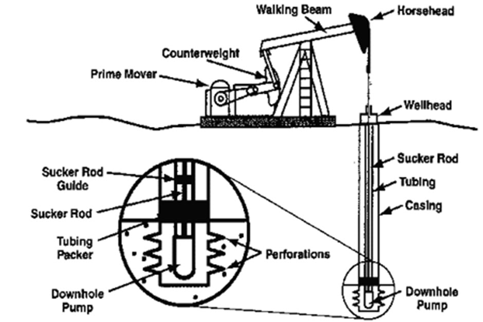
The pumping mode of a sucker-rod pumping system is defined as the combination of pump size, polished-rod stroke length, pumping speed, and rod string design.
the optimum design is based on the value of lifting efficiencies and the one with the maximum ηlift is selected.
Maximizing the lifting efficiency coincides with the case of setting the polished rod power, PRHP, to be a minimum.
for a given hydraulic power
lifting efficiency and PRHP are inversely proportional.
A pumping system design made by this principle results in minimum operation cost and in a maximum of system efficiency.
If the best mode is selected, the energy input at the polished rod is only slightly greater than the pump’s hydraulic power, ensuring a lifting efficiency of over 94%.
The worst mode, on the other hand, requires almost three times as much energy as the best one for lifting the same amount of liquid from the same depth.


by increasing the pump size the attained maximum lifting efficiency values increase for all tapers.
Therefore, use of bigger plungers with correspondingly slower pumping speeds is always useful and results in lower energy requirements.
Also use of the heavier rod strings  increases the power requirement for smaller pump sizes.
OPTIMUM COUNTERBALANCING OF PUMPING UNITS

ideal counterbalance conditions are desired that can have many beneficial effects on the operation of the sucker-rod pumping system:
 Gearbox size can be reduced when compared to an unbalanced condition,
 The size of the required prime mover is smaller, and
   The smoother operation of a properly balanced speed reducer lowers maintenance costs and increases equipment life.
the mechanical Cyclic Load Factor (CLF). It can be calculated from the variation during the pumping cycle of the net torque on the reducer as the ratio of the root mean square and the average net torques:
These methods try to find the maximum counterbalance moment satisfying one of the following criteria:
The peak motor currents are equal during the up-, and downstroke,
 The peak net torques on the up-, and downstroke are equal,
 The required mechanical powers for the up-, and downstroke are equal, or
 A minimum of the cyclic load factor is achieved.
 
The CLF value valid for this case is greater than the minimum CLF achieved by the recommended optimization model.

PITFALLS IN ROD STRING DESIGN 


Rod string design aims at the determination of:
• The rod sizes to be used in the string,
• The lengths of the individual taper sections, and
• The rod material to be used.
The two basic problems in rod string design concern:
(1) how rod loads are calculated, and
(2) what principle to use for the determination of taper lengths.
At the time of design, rod loads are not known, and they also depend on the taper lengths that are about to be determined. Therefore, one has to rely on approximate calculations to find probable rod loads that will occur during pumping

Design Principles
Early rod string design methods utilized the simplifying assumption that the string was exposed to a simple tension loading. An examination of the rod loads during a complete pumping cycle, however, shows that the rod string is under a cyclic loading.
The nature of the loading is pulsating tension because the whole string is under tension at all times, but rod stress levels change for the up-, and the downstroke.
sucker-rod strings should be designed for fatigue endurance.
CONCLUSIONS


The pumping system’s energy efficiency depends primarily on the amount of downhole power losses.
  Maximum system efficiency is ensured by achieving a maximum of lifting efficiency.
 The proper selection of pumping mode can ensure maximum lifting efficiency and thus a most energy-efficient sucker-rod pumping system.
 Optimum counterbalancing of pumping units has many beneficial effects.
Minimizing the CLF is the preferred method for finding optimum counterbalanceconditions.
 Available rod string design procedures can have many pitfalls. Proper designs should provide a uniform fatigue loading of all rod taper sections.

SUCKER ROD PUMP con't

WAYS TO DECREASE PRODUCTION COSTS
FOR SUCKER-ROD PUMPING 
-roughly two-thirds of the producing oil wells are on this type of lift.
-To maximize profits from these wells in the ever-changing economic situation with rising costs of electric power, installation designs must ensure optimum conditions.
IMPROVING ENERGY EFFICIENCY 
energy losses both downhole and on the surface
      must be minimized.

1- Downhole Energy Losses

2- Surface Losses 


-The sources of down-hole energy losses in the
 
sucker-rod pumping system are :
 
-the pump, the rod string, and the fluid column.
 
The energy required for operating the polished
 
rod at the surface  is thus 
 
-the sum of the useful hydraulic work
 
performed by the pump and the downhole 
 
energy losses.
 
-This power is called the polished rod power or 
 
PRHP.
 
-The energy efficiency of the downhole 
 
components of the sucker-rod pumping system can
 
be known by the relative amount of energy
 
losses in the well.
 
This is called Lifting Efficiency.


Surface Losses 
 
 
mechanical energy losses Starting from the polished rod:

frictional losses arise in the stuffing box, in the pumping unit’s

structural bearings, in the speed reducer
 
(gearbox), and in the

 belt drive.
the electrical power taken by the motor is always greater than

 the mechanical power developed at the motor’s shaft.

The power losses in an electric motor are classified as mechanical

         and electrical.

Mechanical losses occur in the motor’s bearings
 
due to friction.

other losses include windage loss consumed by air surrounding the

 rotating parts.

an overall efficiency ηmot is used to represent
all losses in the

 motor, which, for average electric motors,
 
lies in the range of 85% to 93%.  
 
Optimum Energy Efficiency 
 
 
the energy efficiency is found from: 
 
 
Where : 
 
A more detailed formula


—the possible values of both the surface mechanical efficiency, ηmech, 
 
and the motor efficiency, ηmot, vary in

quite narrow ranges.

—At the same time, their values are not easy to improve upon; that is 
 
why. their effects on the system’s total efficiency are not very significant.

—On the other hand, lifting efficiency can be considered as the 
 
governing factor since it varies in a broad range depending on the pumping 
 
mode selected.

—Thus considerable improvements on the pumping system’s overall 
 
energy efficiency can only be realized by achieving a maximum of lifting 
 
efficiency.

—lifting efficiency mainly depends on the pumping mode selected (i.e.
 
the combination of plunger size, stroke length, pumping speed, and rod 
string design). 
 

Sucker Rod Pump

After a period of time from  the natural production of the well , The pressure of the produced zone will be reduced to a value that can't deliver the produced fluid to the surface .
So we will be forced to use any artificial lift method.
Sucker rod pump consider one of the most important and famous one of the artificial methods.
It's a kind of the positive displacement pumps.

The Prime Mover


 Its Function

 Used to Supply the Required mechanical energy which used to lift fluid. This mechanical energy transmitted through the surface equipment to the pump
      Types of Prime Mover
 1-Internal Combustion Engine
2-Electric Motor


 1-Internal Combustion Engine

Internal-combustion engines are the most commonly used prime movers. They are classified as either slow-speed or high-speed engines.
Choosing internal combution engine
1.Available Fuel
2.Equipment Life and Cost
3.Engine Safety Controls
4.Horsepower
5.Installation


2-Electric Motor

Induction electric motors . Horsepower ratings range from 1 to 200 HP,  most motors on pumping units operate at 10 to 75 HP. These are most often three-phase motors
  Electrical Distribution System
Primary
Secondary
grounding
2-The surface Pumping Equipment


Its Function 

1- used to transfer energy from prime mover through sucker rod
string  to the subsurface pump.
2- Changes the rotary motion of prime mover to reciprocating 
motion for the sucker rod 
3-Assures vertical travel of the polished rod string which 
reduces the friction losses at the stuffing box.

-The proper selection of counterbalance is the most important 
aspects of pumping installation design

-The counterbalance weights store energy during the down 
stroke
3- The sucker Rod String 


Its Function

 Used to transmit the energy from surface equipment to the 

down hole pump.


The standard diameters of the sucker rod string are (¾˝,  ,

1.0" ,1  1\8”    , ………………… )


For depths < 3500 ft, We use Untapered rod string.

For depths  >3500 ft , it usually desirable to use a
  tapered rod string.


The smallest diameters placed immediately above the pump


where the rod load is small.


The largest diameters placed at shallow depths where the rod


load is high.


- Advantages of using tapered rod string


1- Decrease the load on the surface equipment than untapered


string.


2-Decrease The  Cost


1- The plunger 

ØIt displace the fluid from tubing to surface during up stroke .
ØPumping cycle = up stroke + down stroke
                             = one turn from unit sheave.
2- The standing valve
* It opens during up stroke due to decreasing in pressure above the valve.
* But during down stroke the pressure of the fluid increase and close the valve.
3- The travelling valve 

ØIt opens during down stroke to lift the fluid in the tubing and It closes during up stroke to lift the fluid to the surface.
ØThe fluid load is transferred from the plunger to the tubing , and this transfer is  a factor in determining the effective plunger stroke.
Theoretical analysis of rod motion:- 

Forces affecting on the polished rod:
1.Dead weight of sucker rod ( wr )
                                                                                                                                                                                                              If sucker rods were suspended statically from
 
a polished rod or if they were rising or falling at 

constant velocity

2. acceleration load ( wa )

  If rods were suspended or move at constant velocity 
 
( wa = 0 ) wa = m.a = ( wr/g ).a = wr .α  
         
 α : acceleration factor
 

the motion of sucker rod string is approximately simple

 harmonic motion as a particle moving with a uniform speed

 around the reference cycle 


The polished rod stroke length is normally stated in inches and the pump speed in strokes per minute. Then


The effective plunger stroke 


plunger and polished rod strokes differ because of rod and tubing stretch and because of plunger over travel resulting from acceleration.
During the upstroke , the travelling valve is closed and the fluid load transferred to rod.
During the down stroke , the travelling valve is opened and the fluid load transferred to the tubing.
The effective plunger stroke is decreased by an amount that equal the sum of rod and tubing elongation resulting from fluid load.
For an elastic deformation
                                            E = stress / strain
E : the modulus of elasticity, is a property of the material to which the stress is applied
                                  
   Stress = F/A
And strain is the fractional change in length ,
                                    Strain =  e/L


And the elongation of the member is 

F : the force on the plunger (acting on the full plunger area ) due to fluid load and can be calculated as follows

Where ∆p  is the pressure difference across the plunger.

If it is assumed that the pump is set at working fluid level in the well and if the fluid depth is L and the fluid specific gravity is G

for the more general case , where working fluid level in the annulus is at depth  D   ,    the pressure
  ( under the plunger ) due to a column of fluid of height ( L – D ) in the casing must be considered :

where ∆p = down force – up force

Tubing elongation

Where At  is the cross sectional area of the tubing wall
Rod elongation ( Untapered )

Where Ar is the cross sectional area of the rods .
For  tapered tube ,


Where en ,  is the elongation of section n having    a 
length of Ln  and   across sectional area of An 
Elongation due to the rod load ,
 The rod load = the dead load of the thread + the 

acceleration load 


Elongation of the rods

The weight of the rod string is
Where ρy  is the density of the rod string which 
is approximately 490 lb/cu.ft . Therefore: 
The effective plunger stroke length ,