Fishing Technology (5)

FISHING FOR JUNK

Overview

Any undesirable object that is stuck or accidentally dropped in a well is
referred to as “junk.” Junk may include bit cones, tong dies, broken slips,
reamer parts or debris created by a fishing or milling operation, or any other
small debris that could impede normal drilling operations. Because of the
wide variety of junk that can be in the hole and the likelihood that the
customer may not know what the junk is, you will have to be fairly creative
in planning a junk fishing operation. However, because of the time and
money spent on fishing operations, you will need to devise a method for
fishing the junk that involves the fewest trips and equipment as possible.


Deciding How to Fish Junk

Evaluating the junk

Any debris or junk in the borehole must be thoroughly evaluated before any
successful fishing attempt can be made. Depending on the properties of the
junk, it can either be milled up, recovered, or pushed back (walled-off) into
the formation.
Consider the following questions before proceeding with a fishing job:
  •  What is the size, weight, and condition of the junk?
  •  Is the junk magnetic?
  •  Can the junk be picked up?
  •  What are the dimensions of the bit cone or cones?
The company man would ideally know exactly what the junk in the hole
consists of. When the nature of the junk is unknown, you must be creative
in your approach to fishing the junk.

 Impact of the junk size, weight, and condition

Try to determine the size, weight, and condition of the junk. This
information will help you determine the best method for fishing the junk.
For example, if you have junk that is:
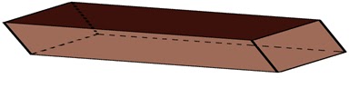
  •  large and/or irregularly shaped, you might try a poor boy basket
  •  smaller, you might try a magnet, core type, or reverse circulating basket.
For very large pieces of junk, you may need to use a junk shot to break it
into smaller pieces before attempting to fish.

Determining if the junk is magnetic

Try to find out what the junk is made of. If it has a high ferrous content, it
is probably magnetic. The easiest method for fishing magnetic junk is using
a magnet.
Determining is the junk can be picked up

If the OD of the junk is significantly smaller than the ID of the hole, than
there is a good chance that it can be picked up. However, if the OD of the
junk is fairly large, it will be harder to get a fishing tool over it. In this case,
you will probably have to mill the junk to break it up and collect the pieces
in a boot basket.

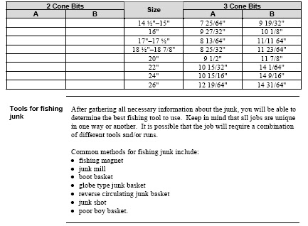
Determining cone dimensions
If you know the junk is a bit cone, the dimensions of the cone must be
known before deciding which tool to run. Find out the size of the bit from
which the cone was lost, and verify the maximum OD of the cone. Select a
tool that has an ID at least 1/8" larger than the OD of the cone.
For example, a 7 7/8" bit cone is 5 15/64" OD. A 7 1/8" OD Bowen Itco
Type Junk Basket has an ID size of 5 28/64". This tool will get over the bit
cone.
Standard rock bit cone dimensions are shown in Table 2-1. Note: This
information can also be found in the Bowen user manuals.


Fishing Technology (4)

Maintaining the Tally Book

Purpose of record keeping

Record keeping is especially helpful when there is a shift change before a
job has been completed. Additionally, records from previous jobs form a
base of information that can be used as a resource when planning fishing
jobs. Record keeping is also important for ensuring that the customer is
billed for the correct equipment and services.

The tally book


The tally book is a short and abbreviated notation of each trip made in the
hole and the tools that were used. The tally book provides important
documentation of the job that is useful for job analysis after the job has been
completed. Additionally, the tally book provides the specifications of the
tools used and services rendered for billing purposes. The tally book should
be kept in such a manner that a relief man could carry on the job with the
information contained in the book.

Rules for keeping the tally book

The tally book must be accurate, legible, and current.
The tally book should include:
  •  a complete description of the fish and all well data
  •  the time, date, number, and brief description of each trip
  •  all parameters, if a milling job is performed. These parameters include:
  1.  depth
  2.  RPM
  3.  strokes per minute (SPM)
  4.  weight on bit (WOB)
  5.  torque
  6.  time
  7.  rate of penetration.
  •  the size and footage along with all auxiliary equipment and daily charges,
if wash pipe is run
  •  a record of any accidents.
Guidelines for the format of the tally book include:
  •  only one trip should be recorded on each page
  •  use one line for each tool description with the OD, ID, length, fishing
neck, and serial number.
The tally book should be kept for future reference.
An example of a tally book 


Fishing resume

The resume is a narrative of the fishing operations and tools that were used
each day. Each trip will be noted along with the outcome of the operation.
The resume is very important because it is the documentation for what the
customer is charged. The billing department will not know what to charge
the customer and the customer will not agree to any charges unless they
have been documented in the resume.
Anything that will be billed to the customer, including estimated repairs or
sold grapples, must be recorded on the resume and signed by the company
man

Signing off on the resume


The company man must sign the job resume when it is completed. We
leave ourselves open to legal action if the company man does not
acknowledge the tools and services that were utilized during the job.

Post-Job Procedures

Completing documentation

The job is not complete until all paperwork, including the resume, and tools
use sheet is completed and signed for.

Breaking down tools

Account for all Weatherford tools. Insure they are loaded in the tool baskets
or loaded on the trucks prior to leaving the job site.
If possible, use the rig tongs to break down all tools that come through the
rotary. Most Weatherford stores do not have the facilities to perform this
operation and vendors charge $100.00 per joint to break down the tools.
However, note that rig time on some offshore rigs is prohibitively expensive
for this operation. For example, when fishing on an offshore rig, especially
in the North Sea, it is cheaper for the customer to be charged for breaking
down the tools at the shop facility.

Transporting equipment


Ensure that all protectors are installed on the tools before transporting them
back to the Weatherford store location. This is important to prevent damage
to exposed threads.
Ensure that only Weatherford property is transported back to the
Weatherford store location. It is difficult to arrange a return trip to bring
equipment that is not the property of Weatherford back to the well site.

Fishing Technology (3)

Fishing Technology Manual

Determining the Amount DOK Required to Reach the Fish

Overview

You will need to determine the amount down on the kelly (DOK) required
to reach the fish in order to design your fishing string. Because you can’t
always rely on the string figures furnished by the customer, it is best to
personally check the figures before beginning operations.

The In and Out Method

The “In” and “Out” method is a good way of checking the string figures for
possible mistakes. The formulas used to calculate the total out and total in
and then the amount DOK required to reach the fish are shown below.


Note: The total “out” must always exceed the total “in” to use this formula.

Example


The following is an example using the “In” and “Out” method for
calculating the depth of the top of the fish.
The customer twisted off while drilling at 4,000 ft. They recovered
3,895.73 feet, including the length DOK. The customer then made a bit trip
and tagged the fish with 37 feet. DOK. To calculate the difference between
the bit run and the following overshot run, subtract the (in) from the (out).
The difference will be the length DOK with overshot run.
See the calculation of the depth of the top of the fish for this example in
Table 1-2


Determining the Kelly Bushing (KB) Measurement


Calculating the original elevation


The standard oilfield measurement to any depth downhole is recorded from
the wellhead, plus the distance to the kelly bushing (KB) on the rig that
drilled the well. This is called the original elevation and is recorded in the
well file.
It is important for everyone to be talking about the same depth. That is why
the total depth is always reported from the original rig elevation. If the
original rig has been replaced by a smaller workover rig, you will need to
account for the difference in this rig’s elevation from the original elevation.


Determining the true well depth


The difference between the original rig elevation and the current rig
elevation is added to or subtracted from the current pipe tally in order to
establish the true well depth. This is called the kelly bushing (KB)
measurement.
For example, assume that the original elevation of a well is 30 feet. The
current elevation is 6 feet. If you start running pipe from the current
elevation, you are already 24 feet into the well. Therefore, in order to reach
a fish that is at a depth of 4,500 feet, you will need to run pipe 24 feet
shorter than 4,500 feet because the depth is measured from the original
elevation (24 feet higher).

Fishing Technology (2)

Fishing Technology Manual

Scheduling Personnel and Equipment

Requirements of the job

When determining the personnel and equipment requirements of the job,
consider previous jobs and possible complications of the job. You may
decide to obtain standby commitments for assets that might be required to
successfully complete the job if the operation does not proceed as initially
planned.

Contact information

The phone number of a contact person on the rig should be secured in case
of any delay or problem lining up the tools. Get good directions to the rig
or boat dock and give the company man a reasonable ETA.

Scheduling required equipment


step:

1-Submit the equipment requirements for the job to the customer’s
operator.
 2-Determine whether or not the rig has sufficient tools.
IF the rig does not have sufficient tools, THEN consider:
- modifying the program and re-submitting the equipment
requirements
- whether Weatherford tools are compatible with the fish and
fishing plan and are available for rental
- special ordering or designing tools.
Note: Consider the time required to design and/or order special
tools and deliver them to the job site.


3-Schedule the delivery of all required tools for the date when
fishing will begin.

Management on Location

Your responsibilities

When you arrive on the rig for a fishing job, you should:
  1.  verify all the pertinent information with the company man and/or tool
    pusher
  2.  check the rig’s equipment
  3.  check the string figures
    During fishing operations, you will need to:
  4.  maintain an accurate fish location
  5.  maintain the tally book
  6.  call in a daily report to the fishing supervisor.
Verifying information

Introduce yourself to the company man and verify all pertinent information
concerning the fish, well, and local conditions. Record the BHA and pipe in
the hole with the company man.
Note: The fishing tool coordinator should be consulted if the company man
does not agree with the Weatherford fishing supervisor’s suggested course
of action. Additionally, the company man must sign the resume when
Weatherford’s suggested course of action is refused.

Checking equipment

Follow the steps below when checking equipment before a fishing
operation.
steps : 
1-The fishing supervisor should personally caliper all tools upon
arrival on location. It is very important to be precise when
callipering tools.
2- Count all pipe on the location and compare with the company
man’s records.
3- Clean out the V door and mark the first joint of pipe on the rack.

4- Count and tie off all pipe in the derrick. The count on the surface
subtracted from the total on location should equal what is in the
hole.


Fishing Technology (1)

Fishing Technology Manual

JOB PLANNING AND RECORD KEEPING


Overview

In fishing jobs, the customer is looking to you to provide an assessment of
the problem and a plan for resolving the problem. They will need you to
respond as quickly and as efficiently as possible so that they can resume
productive operations. You will earn their confidence by being
professional, thorough, and precise in your planning, coordination, and
execution of fishing operations.
At the end of the job, the customer will expect to be charged a fair price for
fishing services. In order to satisfy this need, you will need to plan an
efficient operation and keep accurate records of equipment used and
services performed.

Job Planning

Description

Successful fishing jobs start with excellent job planning. You will need to
do extensive research about the fish and hole conditions before the job is
even started. Appropriate paperwork must be maintained throughout all
phases of the job, including the planning stage.

Purpose

Proper preparation ensures that:
  1. the best option for fishing is determined
  2. time and money are not wasted on an unfishable job
  3. equipment, personnel, and other assets are available when needed.

Components

In planning for a job, you will need to:
  1. gather important information about the job
  2. determine the dimensions of the fish
  3. develop a fishing plan
  4. obtain approval for the fishing plan
  5. schedule personnel and equipment for the operation.

Gathering important information

Several important details should be obtained about the company, job
location, well parameters, work string, fish, and the operation at the time of
the incident. Important questions to ask include:
  1. What are the hole size, angle, and depth?
  2. What are the size, weight, and depth of all casings and liners?
  3.  What are the connections on the work string and drill collars?
  4.  What is the depth and condition of the top of the fish?
  5.  Does the job require jars? Are there jars in the hole? If so, are they working?
Additionally, you should request that a copy of the bottom hole assembly
(BHA) be faxed to you. This document will list everything that is included
in the BHA along with the specifications for each part. This will be
especially important for you to be familiar with because it is often what you
will be fishing out.
When you have gathered all of the job information, research previous
fishing jobs with similar characteristics. The documentation from these jobs
may help you to anticipate problems that may be encountered and learn
about some of the best practices that have been used.

Determining fish dimensions

It is very important to determine all possible dimensions of the fish. This
can be done by obtaining a complete well profile, if one is available.
The following information should be included in the well profile:
  1.  OD, ID, and length of the fish
  2.  OD, ID, and length of the fishing tool assembly
  3.  OD, ID, and length of the work string
  4.  location of the top of the fish
  5.  tensile and torsional strengths of everything that is run into the hole. The strength of the fish must be either memorized or noted in a readily accessible location. You may need to pull this information quickly and not have the time to calculate or research maximum pull values. Remember that pull strength is 80% of the tensile strength.
Other resources for information about the fish include the composite
catalog, technical manuals, and manufacturer’s drawings. These resources
can provide you with the critical points of recovering, burning over, or
milling up the fish. One of the first steps in planning a fishing operation is
studying how the manufacturer recommends releasing or picking up the
specific tool.
Important: You should have an exact replica of the fish (e.g., same type
packer, etc.) delivered to the location. It is far more valuable than drawings,
specification sheets, or photos.

Table 1-1:
Maximum OD of Tools to Run in Casing Excluding Overshots


Enhanced Oil Recovery (Powerwave)

Powerwave

Its a new technique used to improve the performance of waterflooding.
In a perfect world the injection of a liquid would create a piston-like displacement of the remaining oil in place. What actually happens is the non-ideal situation where "fingers" of water bypass the oil.


The Tool Used

a downhole vibration tool based on whirling orbital vibrator.


Operation

Create seismic waves from 5 to more than 500 hertz, and is capable of generating 
controllable force levels up to many tens of thousands of pounds.
The direct mechanical contact with the formation allows the device to transmit the 
vibration energy from the backward whirling mass into the producing formation. 
 
Mechanisms of Increased Recovery
 
 
Changes in Wettability.
Coalescence and/or dispersion of oil drops.
Reduced viscosity
Surface tension


Water Flooding (Enhanced Oil Recovery )


Water Flooding
assume that this has been folded in the middle, so that it now has trapped oil within all the pores of the rock

assuming that I have a layer of rock that is 300 ft thick, five miles wide and thirty miles long , and it has a porosity of 20% .
 
So first let's do a bit of arithmetic :
 300 x 5 x 5280 x 30 x 5280 = 1,254,528,000,000 cu.ft.
 At 20% porosity, this means that some 250,905,600,000 cu. ft. are not rock, and in this case are going to be full of oil.
This is equivalent to 44,685,092,571 barrels of oil.
 
If the oil is light , and the rock properties allow oil to flow easily through the cracks,
Then ,we can recover up to 50% of oil.
So , URR=22.5 billion barrels.
Firstly,well drill vertical wells one quarter of a mile apart.
The total recoverable oil for each well is roughly 10 million barrels


After some years (say;five years) we notice that the volume coming out of the well is not as much as it used to be .
If we pump water into the ground under the oil well, then the water will fill the holes left as the oil leaves, and we can keep the pressure in the oil up, and the oil flow will not drop as fast.


Limits to Water Flooding:

Enhanced Oil Recovery article

What Is It?

Its a term applied to methods used for recovering oil from a petroleum reservoir beyond that recoverable by primary and secondary methods. 

Stages Of Production:

Primary recovery :occurs when a well is initially put into production and the oil flows to surface naturally.


-Secondary recovery :occurs after the reservoir pressure declines and the well no longer flows oil to surface.
-as we take the oil out of the ground, so the pressure in the oil reduces, and the flow slows down.


-Tertiary recovery: involves more technically developed methods such as the injection of steam, chemicals, gases, microbes or heat.

Techniques Involved:

 
EOR includes five methods
Water flooding.
thermal recovery.
 .gas miscible recovery
 chemical flooding .
microbial flooding

   
-The thermal recovery methods are steam flooding, cyclic steam stimulation and in situ combustion.
-The gas miscible recovery methods are carbon dioxide flooding, cyclic carbon dioxide stimulation, nitrogen flooding and nitrogen-CO2 flooding.


-The chemical flooding methods are polymer flooding (including polymer gels), micellar-polymer flooding, and alkaline flooding.
-Microbial EOR methods include microbial flooding and cyclic microbial recovery.
 to be contiued

Enhanced Oil Recovery (EOR) vedio of Powerwave


Enhanced Oil Recovery (EOR) vedio of Powerwave

Its a term applied to methods used for recovering oil from a petroleum reservoir beyond that recoverable by primary and secondary methods.Powerwave


enhanced oil recovery eor techniques enhanced oil recovery eor technologies enhanced oil recovery eor processes 
enhanced oil recovery eor offshore enhanced oil recovery eor by miscible co2 and water flooding of asphaltenic and non-asphaltenic oils enhanced oil recovery eor methods  enhanced oil recovery economics enhanced oil recovery pdf enhanced oil recovery equipment enhanced oil recovery environmental issues

Introduction to ECLIPSE 100

ECLIPSE 100 is a fully-implicit, three phase, three dimensional, general purpose black oil simulator with gas condensate option.


Program is written in FORTRAN77 and operate on any computer with an ANSI-standard FORTRAN77 compiler and with sufficient memory.


ECLIPSE 100 can be used to simulate 1, 2 or 3 phase systems. Two phase options (oil/water, oil/gas, gas/water) are solved as two component systems saving both computer storage and computer time. In addition to gas dissolving in oil (variable bubble point pressure or gas/oil ratio), ECLIPSE 100 may also be used to model oil vaporizing in gas (variable dew point pressure or oil/gas ratio).


Both corner-point and conventional block-center geometry options are available in ECLIPSE. Radial and Cartesian block-center options are available in 1, 2 or 3 dimensions. A 3D radial option completes the circle allowing flow to take place across the 0/360 degree interface.


How to start?

To run simulation you need an input file with all data
concerning reservoir and process of its exploitation.


Input data for ECLIPSE is prepared in free format using a keyword system. Any standard editor may be used to prepare the input file. Alternatively ECLIPSE Office may be used to prepare data interactively through panels, and submit runs.


The name of input file has to be in the following format: FILENAME.DATA

 to complete


Seismic waves


body waves
P-waves (longitudinal, compressional)
S-waves (shear, transverse)
SV-wave
SH-wave

Different kind of waves


Examples of different waves


Surface waves


Newton’s law


P is the acoustic pressure
Uz is the displacement


Hooke’s law


Acoustic Expressions


Acoustic expressions
with source term


Acoustic Wave equation


be conitued

SEISMIC

Seismic Data Processing


next


next


next


Applied Reservoir Engineering free download

Applied Reservoir Engineering


Dr. Hamid Khattab


INTRODUCTION TO RESERVOIR SIMULATION


Analytical and numerical solutions of simple one-dimensional, one-phase flow equations
As an introduction to reservoir simulation, we will review the simplest one-dimensional flow equations for
horizontal flow of one fluid, and look at analytical and numerical solutions of pressure as function of position
and time. These equations are derived using the continuity equation, Darcy's equation, and compressibility
definitions for rock and fluid, assuming constant permeability and viscosity. They are the simplest equations we
can have, which involve transient fluid flow inside the reservoir.
Linear flow
Consider a simple horizontal slab of porous material, where initially the pressure everywhere is P0 , and then at
time zero, the left side pressure (at x = 0 ) is raised to PL while the right side pressure (at x = L) is kept at
PR = P0 . The system is shown on the next figure:


Partial differential equation (PDE)
The linear, one dimensional, horizontal, one phase, partial differential flow equation for a liquid, assuming
constant permeability, viscosity and compressibility is:
Transient vs. steady state flow
The equation above includes time dependency through the right hand side term. Thus, it can describe transient, or
time dependent flow. If the flow reaches a state where it is no longer time dependent, we denote the flow as steady
state. The equation then simplifies to:


Transient and steady state pressure distributions are illustrated graphically in the figure below for a system where
initial and right hand pressures are equal. As can be observed, for some period of time, depending on the properties
of the system, the pressure will increase in all parts of the system (transient solution), for then to approach a final
distribution (steady state), described by a straight line between the two end pressures.
Analytical solution to the linear PDE
The analytical solution of the transient pressure development in the slab is then given by:

It may be seen from the solution that as time becomes large, the exponential term approaches zero, and the
solution becomes:


This is, of course, the solution to the steady state equation above.
Radial flow (Well test equation)
An alternative form of the simple one dimensional, horizontal flow equation for a liquid, is the radial equation that
frequently is used for well test interpretation. In this case the flow area is proportional to r2, as shown in the
following figure:


The one-dimensional (radial) flow equation in this coordinate system becomes

For an infinite reservoir with P(r Æ•) = Pi and well rate q from a well in the center (at r=rw) the analytical
solution s