
After a period of time from the natural production of the well , The pressure of the produced zone will be reduced to a value that can't deliver the produced fluid to the surface .
So we will be forced to use any artificial lift method.
Sucker rod pump consider one of the most important and famous one of the artificial methods.
It's a kind of the positive displacement pumps.

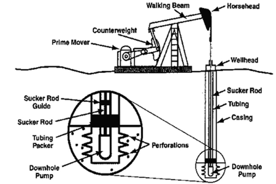
The Prime Mover
Its Function
Used to Supply the Required mechanical energy which used to lift fluid. This mechanical energy transmitted through the surface equipment to the pump
Types of Prime Mover
1-Internal Combustion Engine
2-Electric Motor
1-Internal Combustion Engine
Internal-combustion engines are the most commonly used prime movers. They are classified as either slow-speed or high-speed engines.
Choosing internal combution engine
1.Available Fuel
2.Equipment Life and Cost
3.Engine Safety Controls
4.Horsepower
5.Installation
2-Electric Motor
•Induction electric motors . Horsepower ratings range from 1 to 200 HP, most motors on pumping units operate at 10 to 75 HP. These are most often three-phase motors
Electrical Distribution System
Primary
Secondary
grounding

2-The surface Pumping Equipment
Its Function
1- used to transfer energy from prime mover through sucker rod
string to the subsurface pump.
2- Changes the rotary motion of prime mover to reciprocating
motion for the sucker rod
3-Assures vertical travel of the polished rod string which
reduces the friction losses at the stuffing box.
-The proper selection of counterbalance is the most important
aspects of pumping installation design
-The counterbalance weights store energy during the down
stroke
3- The sucker Rod String
Its Function
Used to transmit the energy from surface equipment to the
down hole pump.
The standard diameters of the sucker rod string are (¾˝, ,
1.0" ,1 1\8” , ………………… )
For depths < 3500 ft, We use Untapered rod string.
For depths >3500 ft , it usually desirable to use a
tapered rod string.
The smallest diameters placed immediately above the pump
where the rod load is small.
The largest diameters placed at shallow depths where the rod
load is high.
- Advantages of using tapered rod string
1- Decrease the load on the surface equipment than untapered
string.
2-Decrease The Cost

1- The plunger
ØIt displace the fluid from tubing to surface during up stroke .
ØPumping cycle = up stroke + down stroke
= one turn from unit sheave.
2- The standing valve
3- The travelling valve
ØIt opens during down stroke to lift the fluid in the tubing and It closes during up stroke to lift the fluid to the surface.
ØThe fluid load is transferred from the plunger to the tubing , and this transfer is a factor in determining the effective plunger stroke.


Theoretical analysis of rod motion:-
—Forces affecting on the polished rod:
—
—
1.Dead weight of sucker rod ( wr )
If sucker rods were suspended statically from
a polished rod or if they were rising or falling at
constant velocity
2. acceleration load ( wa )
If rods were suspended or move at constant velocity
( wa = 0 ) wa = m.a = ( wr/g ).a = wr .α
α : acceleration factor
the motion of sucker rod string is approximately simple
harmonic motion as a particle moving with a uniform speed
around the reference cycle
—The polished rod stroke length is normally stated in inches and the pump speed in strokes per minute. Then

The effective plunger stroke
—plunger and polished rod strokes differ because of rod and tubing stretch and because of plunger over travel resulting from acceleration.
—During the upstroke , the travelling valve is closed and the fluid load transferred to rod.
—
—During the down stroke , the travelling valve is opened and the fluid load transferred to the tubing.
—The effective plunger stroke is decreased by an amount that equal the sum of rod and tubing elongation resulting from fluid load.
—
—For an elastic deformation
E = stress / strain
E : the modulus of elasticity, is a property of the material to which the stress is applied
Stress = F/A
And strain is the fractional change in length ,
Strain = e/L

And the elongation of the member is

—F : the force on the plunger (acting on the full plunger area ) due to fluid load and can be calculated as follows

—Where ∆p is the pressure difference across the plunger.

—If it is assumed that the pump is set at working fluid level in the well and if the fluid depth is L and the fluid specific gravity is G

—for the more general case , where working fluid level in the annulus is at depth D , the pressure
( under the plunger ) due to a column of fluid of height ( L – D ) in the casing must be considered :
—where ∆p = down force – up force

—Tubing elongation

Where At is the cross sectional area of the tubing wall
—Rod elongation ( Untapered )
—Where Ar is the cross sectional area of the rods .
—For tapered tube ,
—Where en , is the elongation of section n having a
length of Ln and across sectional area of An
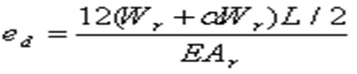
—Elongation due to the rod load ,
The rod load = the dead load of the thread + the
acceleration load

—Elongation of the rods
—The weight of the rod string is
—Where ρy is the density of the rod string which
is approximately 490 lb/cu.ft . Therefore:

—The effective plunger stroke length ,
