INTRODUCTION TO RESERVOIR SIMULATION


Analytical and numerical solutions of simple one-dimensional, one-phase flow equations
As an introduction to reservoir simulation, we will review the simplest one-dimensional flow equations for
horizontal flow of one fluid, and look at analytical and numerical solutions of pressure as function of position
and time. These equations are derived using the continuity equation, Darcy's equation, and compressibility
definitions for rock and fluid, assuming constant permeability and viscosity. They are the simplest equations we
can have, which involve transient fluid flow inside the reservoir.
Linear flow
Consider a simple horizontal slab of porous material, where initially the pressure everywhere is P0 , and then at
time zero, the left side pressure (at x = 0 ) is raised to PL while the right side pressure (at x = L) is kept at
PR = P0 . The system is shown on the next figure:


Partial differential equation (PDE)
The linear, one dimensional, horizontal, one phase, partial differential flow equation for a liquid, assuming
constant permeability, viscosity and compressibility is:
Transient vs. steady state flow
The equation above includes time dependency through the right hand side term. Thus, it can describe transient, or
time dependent flow. If the flow reaches a state where it is no longer time dependent, we denote the flow as steady
state. The equation then simplifies to:


Transient and steady state pressure distributions are illustrated graphically in the figure below for a system where
initial and right hand pressures are equal. As can be observed, for some period of time, depending on the properties
of the system, the pressure will increase in all parts of the system (transient solution), for then to approach a final
distribution (steady state), described by a straight line between the two end pressures.
Analytical solution to the linear PDE
The analytical solution of the transient pressure development in the slab is then given by:

It may be seen from the solution that as time becomes large, the exponential term approaches zero, and the
solution becomes:


This is, of course, the solution to the steady state equation above.
Radial flow (Well test equation)
An alternative form of the simple one dimensional, horizontal flow equation for a liquid, is the radial equation that
frequently is used for well test interpretation. In this case the flow area is proportional to r2, as shown in the
following figure:


The one-dimensional (radial) flow equation in this coordinate system becomes

For an infinite reservoir with P(r Æ•) = Pi and well rate q from a well in the center (at r=rw) the analytical
solution s


Oil and Gas Well Completions cont 1

Tubing Hanger/Xmas Tree Interface


Adapter Flange

Cross-over between tubing hanger spool and x-mas tree
It can receive the extended tubing hanger neck
Feed through for:
electrical cables (ESP or sensors)
hydraulic controllines (sc-sssv)
sensor lines etc 
Surface Wellhead Connectors


The completed well


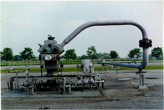
Xmas Trees

Primary flow control system for well once in production
Features and access requirements
Outflow from well - production
Inflow to well - injection or killing
Vertical access to tubing - wire line, coiled tubing
Flanged Xmas Tree 
Xmas Tree Components 
Pressure gauges (accessory)
safety hazard / potential wrong pressure readings
Gauge flange or tree cap
provides seal for top of tree
Lubricator valve
isolate pressure, well access for intervention tools
Flow tee
used to direct flow, enable thru-tubing access
Production wing valve
used to isolate well for most routine operations 
Kill wing valve
enables connection of pumping equipment
Choke (accessory)
controls rate of flow from well
Master valves (main isolation valves)
Upper Master Valve (operational valve), optional: hydraulic / pneumatic controlled
Surface Safety Valve
Lower Master Valve (back-up valve)
  manually operated


 X-mas tree valve


¥The stem rotates
¥The gate moves up and down
 
 Choke


Categories of Xmas Tree 

Flanged tree
Several flanged components
each connection is a potential leak path
Much more common than monoblock design
More flexible than monoblock design
takes up more space (height)
Monoblock construction tree
Single block construction
Fewer possible leak paths
Used in high pressure/leak sensitive locations
 
  Monoblock Xmas Tree
 
Comprises inline or "Y" shaped block of single casting/forging
Valving arrangement
Lower Master Valve (manual)
Upper Master Valve (Surface Safety Valve)
Y piece or side outlet flanges
houses both production and kill wing valves
Uppermost valve (manual swab valve)
  Well cluster in shallow water
WELL IN CELLAR


Tree hook-up
Multiple Completions


Cases where more than one completion string installed
Each string independently suspended
Must seal off tubing casing annulus
either independently or collectively
Independent control of fluid flow in each string
Multiple Completion Tree


Xmas Tree Selection
produce a listing of the parameters of the anticipated process or 
operating envelope
- Classify the Well Type
  Water Well ( low or medium pressure, Rate )
  Oil Well (low, medium or high pressure, GOR, Rate )
  Gas Well ( low, medium or high pressure, WGR, Rate)
This will be the basis for the design and the selection of equipment 
type and rating
 

KEYWORDS
tubing suspension
annulus access
hanger flange
boll weevil
ram type
LMG, UMG, Swab valve
production and kill wing valve
surface safety valve
flanged and monoblock tree
pressure rating


Oil and Gas Well Completions

Gas Lift Optimization cont 1

Wells that can only Flow under gas Lift


WTEST can be used to revive a dead well by adding lift gas
The WIG  is calculated based on the total number of lift gas increments that would give the well the largest ratio of oil production rate to lift gas injection rate (line 
O-A)
If a well is only just able to flow (at point B), the WDG is calculated based on all the increments (line O-B)
Using the GLO Facility (1)


Prepare the VFP Tables - VFPPROD
ALQ = lift gas injection rate (GRAT)
VFPTABL
1 = Linear interpolation
2 = Cubic Spline interpolation
LIFTOPT keyword
Activates the GLO facility
Sets: 
incremental size for lift gas injection rate
Min economic gradient
Min interval between GLOs
GLO during each of the 1st NUPCOL iterations?
 WLIFTOPT keyword 
Well name 
Is the well to be optimized using GLO? 
Max lift gas injection rate 
Weighting factor for preferential allocation of lift gas 
Min lift gas rate 
>0 = Min rate unless the well cannot flow 
<0 = at least enough lift gas to enable the well to flow 
allocate in decreasing order of weighting factor to group of wells 
Note: By default, no lift gas is allocated if the group’s target can be met unless the weighting factor > 1.0
GLIFTOPT keyword (optional)
group lift gas supply limits
group lift gas rate = SUM well lift gas rate x efficiency factor
maximum total (produced + lift ) gas rate for the group
Group Production Rate Limits
Lift gas is allocated if a group/field cannot reach its OPR
subject to lift gas supply limits, other phase limits (unless 
necessary to make the well’s Min lift requirement & the well’s
 weighting factor > 1.0)
Rates could change if GLO is only in the 1st iteration
Use with network option
GLO when the network is being balanced 
if the network is only balanced in the 1st iteration, GLO is only in the start of the time step
if the network is only balanced in the 1st NUPCOL iterations, GLO will also be carried out in the 1st NUPCOL iterations
Computing time increases with (No. wells)2
effect of lift gas in pipe line:
item 6 of GRUPNET
‘FLO’ = add wells’ lift gas to the branch. The total GFR is used in VFP table
‘ALQ’ = total ALQ = SUM of wells’ ALQs = the total ALQ is used in VFP table
  
Output
Gas lift injection rate: FGLIR, GGLIR, WGLIR
well oil gas lift ratio: WOGLR 
FGPR & WGPR do not include injected lift gas
Restrictions
Do not use
GLIFTLIM - Max(sum ALQ), Max No. wells on artificial lift
the lift switching option in WLIFT
Use GLIFTOPT and WLIFTOPT instead
Flux Boundary Conditions facility should no be used
lift gas supplied to wells outside the flux boundary is not taken into account