Showing posts with label Well completion stimulation course. Show all posts

Chapter 3: Cementing con't lec ( 12 )

Cementing Calculations

The following calculations follow the formulas used in the cementing monograph.’ Buoyant force on the casing by the fluid in the hole tries to float the casing. Hydrostatic pressure acts
against the effective area of the casing, causing the upward force. The pressure acts on the full area of the closed end casing if the float is in place and holding or on the area created by do-di if the casing is open ended. The weight of the casing string minus the upward buoyancy force gives the buoyed or true weight of the casing string in the hole.

For 13-3/8 in., 61 Ib/ft, K-55 casing in a 17 in. hole, filled with 10 Ib/gal mud:
    closed end area = x (do2/4) = 141 in.2
    effective area = (1/4)x (do2-di2) = 17.5 in.2
     hydrostatic at 4000 ft = 4000 ft (1 0 x 0.052 psi/ft = 2080 psi
    hydrostatic effect on casing = 2080 psi x 17.5 in? = 36,400 Ib
     casing string weight on air = 61 Ib/ft x 4000 ft = 244,000 Ib
The buoyed weight of the casing in mud divided by the outside area of the casing gives the pressure needed to balance the string:
                                                 207,600 lb/141 in.2 = 1472 psi

Thus, a bottomhole kick or other pressure increase of over 1472 psi (additional 0.368 psilft or 7.1 Ib/gal) could start the casing moving upwards. At shallower depths, especially with large diameter casing, the additional pressure to lift the buoyed weight can be 100 psi or less. The pressure to land the top plug when displacing 16 Ib/gal cement with fresh water to 4000 ft (assuming complete annulus fill with cement) is:
cement hydrostatic in annuls = 4000 ft x 16 Ib/gal x 0.052 .@ = 3328 psi
water hydrostatic in casing = 4000 ft x 8.33 Ib/gal x 0.052 lbft = 1733 psi
pressure to land plug = 3328 - 1733 = 1595 psi lb ft psi gal
In wells where a1 the exposed formations will not support the full weight of the cement while fracturing, the cement must be lightened or the zone must be protected by only filling the annulus with a partial column of cement (staged cementing). Assume the zone at 4000 ft (bottomhole) has a fracture gradient of 0.72 psi/ft. Calculate the height of
a 16 Ib/gal cement column that will be 200 psi below fracturing pressure:
bottomhole frac pressure = 4000 ft x 0.72 psi/ft = 2880 psi
allowable bottomhole pressure = 2880 psi - 200 psi = 2680 psi
cement gradient = 16 Ib/gal x 0.052 = 0.832 psi/ft
full column pressure = 4000 ft x 0.832 psi/ft = 3328 psi
If 16 Ib/gal cement is used, the maximum column height (within the allowable pressure) is:
column height = 2680 psV0.832 psi/ft = 3221 fl
If a full cement column is needed, the maximum cement density is:
maximum density = 2680 psi/4000 ft = 0.67 psi/ft or 12.9 lblgal
Cement densities are only part of the picture, the friction pressures developed by pumping the cement past restrictions adds to the hydrostatistic pressure of the cement.
Balanced Plug Setting
 Determining the height that cement will rise where it can equalize height requires use of a simple balanced plug formula.

Squeeze Cementing
Squeeze cementing forces a cement slurry behind the pipe to repair leaks or shut of fluid loss Squeeze cementing is normally thought to be a repair step, but is also used to seal off depleted zones or unwanted fluid production. Smith2 documents eight major uses of squeeze cementing for repair and recovery control purposes:

1- To control high GORs. By squeezing the top section of the perfs, gas production can be made to pass vertically through the top part of the formation matrix, slowing the gas production by the contrast in vertical vs. horizontal permeabilities.
2- To control excessive water, squeezing lower perfs can delay water production. Only if an impenetrable barrier separates the oil and water or if vertical permeability is very low, will effective water reduction be achieved.
3- Repairing casing leaks. Cement can be squeezed through holes in casing. This is best accomplished by very small particle cement.
4- To seal thief zones or lost-circulation zones. Cement slurry may penetrate natural fractures for only a centimeter or two but may develop sufficient blockage to help control leakoff. The cement slurry bridges on the face of the matrix. Sealing off natural fractures is often difficult.
5- To stop fluid migration from a separate zone. This is usually a block squeeze or channel repair operation.
6- Isolation of zones. Selective shutoff of depleted or abnormally low or high pressure zones.
7- Repair of primary cement job. Filling voids or channels, and repair of liner tops are common.
8- Abandonment squeezes. Shutting off depleted reservoirs or protecting fresh water sands.

Squeeze cementing is separated into high pressure squeezing and low pressure ~ q u e e z i n g . ~ ’ ~ ~ ~
High pressure squeezing involves fracturing the formation with cement until a required surface pressure is reached. The importance of high pressures at the end of the job, although popular with many companies, is actually of little importance and should be well below 1 psi/ft.32333 The high pressure squeeze uses “neat” cement (no additives) with very high fluid loss. The best use of the technique is usually to shutoff depleted zones and to seal perforation^.^^ The low pressure squeeze technique is probably more efficient in placing a controlled amount of cement in a problem area of the well. With this technique, formation fracturing is completely avoided. The pressure is achieved by pressuring-up on the cement and allowing the cement to filter out on the formation creating a block in the annulus. Once the cement slurry has hardened or dehydrated to a sufficient extent, no more fluid will be displaced. The excess cement that is still the drill pipe or the annulus can be displaced from the well by opening the casing valve and flushing with a displacement fluid. The advantages of the low pressure squeeze are less pressure exposure to tubing and casing and special cementing tools, and a smaller quantity of cement. For either of the squeeze cementing process, a relatively low water loss, strong cement is part of the design. Most operations use nonretarded API Class A, G or H, which are suitable for squeeze conditions
to 6,000 ft without additives. For deeper wells, Class G or H can be retarded to gain necessary pumping time. In hotter wells (above 230°F), additives should be considered at high temperature to increase strength.
Although squeeze cementing is often used to help repair primary cement failures to protect the pipe, it is possible to collapse the casing during squeeze cementing. If a packer is set immediately above the zone to be squeezed and an open channel exists that links the backside of the casing above the packer to the interval being squeezed Figure 3.14, then the outside of the casing above the packer may be exposed to the full pressure of the cement squeeze. If the inside of the casing is not be loaded or pressurized, casing failure can occur if the Ap is above pipe strength.

The thickening time and set time of cement used in squeeze operations are calculated in the same manner as those used in primary cementing. Squeeze pressure does effect the dehydration of the slurry, particularly across zones which are very permeable. Fluid loss additives may be included if the slurry is designed to move any significant distance across a permeable formation. Normal dehydration of a cement on a permeable section is severe enough to seal off the flow channel before complete displacement is accomplished.
Cement Squeeze Tools

A drillable or retrievable cement retainer is a modified packer that helps control the placement of cement and protects other zones from pressure and excess cement. Retrievable tools can be set and released several items and can be used for several squeeze repairs in one trip. Drillable tools are a single use tool that stays in place and is drilled out (if needed) after the cement has set. The tools are modified packers and are available in compression set and tension set models. Compression set models
are normally used below 3000 ft where the weight of the string is adequate to completely engage the slips. Drillable cement tools are more restricted in setting and application than retrievables but offer more control on the set cement. The drillable models are preferred where continued pressure must be maintained after squeezing. When squeezing formations that are naturally fractured, it is more important to fill the fractures rather than buildup a filter cake.’ Smith’ cites a two slurry system as successful in fractures: a highly accelerated slurry and a moderate- fluid-loss slurry. Accelerated slurries are pumped into the zones of least resistance and allowed to take an initial set. After the first slurry has gelled, the moderate fluid loss slurry is forced into the narrower fractures. The first slurry used for this type of squeeze should take an initial set 10 to 15 minutes after placement.

Liner Cementing

Cementing of liners requires special equipment and techniques to obtain a seal in the close clearances found between the liner and the open hole or the casing string. For more information, the reader is referred to a set of articles by Bowman and Sherer, published in World 47-54 Two cementing techniques are use for liner cementing; a modified circulation job (looks much like a cement squeeze) and a puddle cement technique. In the circulation/squeeze, Figure 3.1 5, the liner and associated equipment is run on drill string with a liner running tool and a retrievable packer assembly. After the base of the liner is squeezed, usually up to the shoe of the outer casing or slightly above, the liner running tool is pulled out of the liner up to a point just above the liner top and the top section of the liner is squeezed. After drillout of the remaining cement, a liner packer, may be run.

Cementing liners, especially deep liners at high pressures, is complicated since the liner is often isolated from the rest of the string by packers and close clearances. The result is that pressures are often trapped behind the pipe. Pipe collapse and deformation are ~ o m m o n .L~in~er, c~em~e nting technology is little different from full string technology except that pipe movement (including rotation) is done on drill pipe40r43 and use of plugs requires two part plugs. Liner tie back operations may require special circulating guidelines because of the narrow clearance^.^^ Liner hanger clearances near the top will be critical in minimizing backpressure if the cement is circulated around the top of the liner in a complete circulation job. Close clearances created by a large liner hanger can raise the backpressure and the equivalent circulation density. In some cases, this increase in equivalent density is enough to fracture the well. In a puddle job, the cement slurry is spotted by the drill pipe over the section in which the liner is to be run. The volume calculation for the puddle of cement must consider hole volume and liner volume. Undetected washouts in the hole can lead to lack of cement around the liner top. Although the procedure is much simpler than the  circulation/squeeze technique, it is also often less effective in providing a seal. The technique is used for short liner sections.
 Frictional Pressure Dropin Pipe
 The pressure drop of general slurries in pipe is given by:

Chapter 3: Cementing lec ( 11 )


Cementing is one of the most critical steps in well completion. Sadly, coming at the end of drilling and in the haste to put a well on production, rarely is the time and commitment taken to get a good job. We then spend significantly more time correcting it or battling the effects of a bad cement job. Cement fills and seals the annulus between the casing string and the drilled hole. It has three general purposes:
 (1) zone isolation and segregation,
 (2) corrosion control, and
 (3) formation stability and pipe strength improvement.
 Cement forms an extremely strong, nearly impermeable seal from a thin slurry. The properties of the cement slurry and its behavior depends on the components and the additives in the cement slurry. This chapter will focus on the basics of the cementing process. For further information on cement and the cementing process the reader is referred to the Society of Petroleum Engineering’s Cementing Monograph.’
Most cements used in the oil industry are a type of portland cement. The name portland was taken from an English channel island with a limestone quarry that was used as source of stone for the development of portland cement. Portland cement is produced from limestone and either clay or shale by roasting at 2600 to 3000°F. The high temperature fuses the mixture into a material called clinker cement.’ After the roasting step, the rough clinker product is ground to a size specified by the grade of the cement. The final size of the cement particles has a direct relationship with how much water is required to make a slurry without producing an excess of water at the top of the cement or in pockets as the cement hardens. The crystals seen in set cement include:’ C3S - tricalcium silicate, C2S - dicalcium silicate, C4AF - tetracalcium aluminoferrite, C3A - tricalcium aluminate, MgO - periclase or magnesium oxide, and CaO - free lime. Not all cements, even those made from the same components, will react in the same manner when mixed with water. Basically, the differences are in the fineness of the grind of the cement, impurities in the water and in some minor additives added during the cement manufacturing process. Figure 3.1 gives the API designated classes for cements. These classifications of cement were in response to deeper and hotter downhole conditions. Note that the useful depths given in the data are derived from average pumping times of neat (no additives) cement for average temperatures involved at these depths. Actual well  environment controls the limits of the cement. Also, additives such as accelerators and retarders can be used to modify the behavior of the cement. In this manner, a class H  cement, for example, can be used to much greater depths than the 8000 ft limit seen in the table.

Figure 3.1: API Cement Classes


There are a number of other cements that do not fall specifically into any general   classification. These cements are special blends of portland and additives or cements based on other chemistry. They include pozzlin cement, which incorporates organic resin  technology, expanding cements, which increase in volume as the cement sets, silica and lime cement for hot wells, and low heat generating cements for permafrost applications. These cements are rarely used in general completions because they are more expensive than portland or have other traits that are less desirable than those of portland.
Environmental conditions and available completion equipment may significantly affect the performance of the cement or place special requirements on the cement. The unique problems of the effect of temperature on cement setting and long-term strength of cements have led to development of special cements for both steam wells and those in arctic environments. High temperatures sharply reduce cement strength and durability, necessitating the development of stabilizers. Silica additives and lime based cements have proved effective in thermal wells. Permafrost cement was developed in response to a need to cement formations to depths of 2000 ft without producing sufficient heat of hydration from
setting the cement to melt and destabilize the permafrost. The most important aspect of cementing blending is obtaining a consistent slurry with the proper amount of additives and mix water. The optimum water-to-cement ratio for a cement slurry is a compromise.
Maximum cement strength occurs at a water-to-cement ratio of about 2.8 galhack. This is
the minimum amount of water necessary to fully hydrate and chemically react with the cement ground to a size that represents Class G. But, a slurry mixed at this water rate has a very high viscosity and cannot be pumped. If too much water is used to aid in pumping and displacement, low strength and a very high free water quantity will occur. The tradeoff between cement strength and the mixing water volume is seen in the data of Figure 3.2.* Free water is defined as water that is not needed by the cement for reaction. When flow stops, it separates out to the top of the cement column. Separation may occur at the top of a long column or in pockets in highly deviated w e k 3 These pockets contribute to annular gas leakage and other annular flow problems. Cement is mixed by jet mixers that combine cement and water in a single pass operation or the more precision batch mixers that mix by circulating in a large tank but only mix a limited volume at a time.' Although an acceptable slurry can be achieved in the jet mixer by an experienced operator, the batch mixer allows closer control in critical, small jobs. The jet mixers' are used for almost all large jobs that
require a constant supply of cement slurry at a high rate. The density of slurries mixed by these methods must be checked periodically with a pressurized mud balance to obtain consistent density. Density is important to control the reservoir pressure and prevent formation fracture breakdown. The quality of the water used to mix the cement varies widely depending upon the specifications required by the company involved. Fresh water, seawater and some brackish waters are used to mix cement slurries. For any source of water, the behavior of the resultant cement in terms of setting time and pumpability must be known before mixing. Pumpability is measured by a laboratory instrument called a  con~istometerT.~h is device measures the setting time of a cement slurry by stirring the slurry (under pressure) until it thickens too much to stir. The output is as units of consistency, and is time related. This test yields the time that a particular slurry can be pumped at a given temperature. Because of the development of offshore fields, seawater has become very widely used for cementing. Seawater, like most inorganic salt brines, slightly accelerates the set time of cement. Fortunately, as

shown in Figure 3.3, the chemical composition of seawater throughout the world does not vary to a large degree,5 but some chemical additive additions may be necessary to control effects of salt and temperature. Use of brackish water (from bays, swamps, sewage or produced waters) can cause problems. High salt contents, especially calcium chloride, may decrease the cement set time. Organic contaminates (such as oil-base mud) may slow the cement set time, sometimes so severely that the slurry does not set.

Accelerators or retarders may be used in the cement to change the set time from a few minutes to many hours. A retarder is used in deep or very hot wells to prevent the set of the cement before the job is complete. Accelerators are used in shallow or cool wells to speed up the set of cement so less rig time is lost waiting on the cement to set. Values such as filtrate loss control and cement expansion can also be directly affected. Cement additives may be divided into two general classifications based on their reaction type; chemical and nonchemical. Nonchemical additives are usually materials which affect the cement by altering density or controlling fluid loss. Chemical additives modify the hydration
(water intake). 
Cement Density

Controlling the cement slurry density is critical for placing a column of cement where the formation may be fractured by a heavy slurry or would allow the well to flow if the cement slurry was lighter than the pore pressure. For a lighter weight cement than the normal 15 to 16 Ib/gal, bentonite clay may be added to absorb water to yield a lighter cement with higher bound water volume. Ten to 12 Ib/gal cement density can be achieved in this manner. Grinding the cement to a very small size will also require more water to satisfy the high surface area and lighten the slurry to the 10 to 12 Ib/gal range. Ultra-light-weight cement^,^'^ using hollow ceramic or glass beads can reduce the overall weight of
the cement slurry to less than 9 Ibs per gallon. Even lower densities can be achieved by foaming the cement with a compressed gas such as nitrogen.&’’The foamed cements can create densities of 4 to 7 Ib/gal but require careful control of annulus surface pressures to avoid gas channels and voids. All these light weight cements, although strong enough to support the pipe, have less strength than the regular portland cement. Heavy weight materials are added to the cement to increase the cement density, usually to control the pressure in the formation during the pumping of the cement. Iron ore, barite (barium sulfate) and sand can create slurries to 25 Ibs/gal. Other methods of preparing heavyweight slurries include the use of dispersants which allow less water to be used in a cement and still  maintain pumpability. A chart of cement density for various methods of density control is contained in Figure 3.4.


In some treatments where the light weight cements are not used either by preference, economics or  for reasons of strength, stage tools can be used to control the pressures on a zone by running a multistage cement job. A staged job separates the cement job into small cement jobs that only support a portion of the total column and weight. The tools prevent the cement columns from contacting each other until set. An example of a cement stage tool is seen in Figure 3.5. The simplest tool uses a drillable plug to seal the pipe below the tool and to open a set of ports that allow the next cement stage to turn the corner and start up the annulus. Some tools are equipped with a seal device that prevents cement from falling down the annulus and ruining the job by creating channels or by exerting more pressure on the lower zones. With these tools, even a deep well with several zones can be cemented by turning the job into several consecutive jobs. The staged concept can also be done by cementing with a small volume and perforating the pipe above the last cement top and repeating the process. However, the tools save WOC time between jobs. The obvious drawback to the tools is the same for all downhole tools; reliability.
Fluid Loss 
Lost circulation materials control the flow of whole cement into natural fractures or extremely large vugs. The control materials come in three basic types: granular, lamellated and fibrous. Granular materials such as sand and other products set a secondary matrix by filling cracks and vugs in the formation. They may have a size range from 1/4 in. diameter to fine powder to achieve control. Lamellated or flaked products such as shredded cellophane stopped at the formation face and create a blockage on which cement will form a filter cake. Fibrous material such as paper, nylon or polypropylene are best suited to bridge small fractures.

can be lost waiting on cement (WOC) to set. This WOC time can be shortened by the use of accelerators. Cement requires very little strength to physically support the casing. More strength is required in withstanding loading from drill bits and pressure. In designing the cementing operation, it is imperative that high strength cements be used around the casing shoe (the bottom end of the pipe) and across potential pay, thief zones (areas of fluid loss) and water producing zones. Filling the annulus behind pipe and zone separation requires very little strength and more economical cements or cement extenders may be used.
While the cement slurry is liquid, the hydrostatic force from the weight of the slurry exerts force to prevent entry of gas into the wellbore annulus. When pumping stops, the cement starts to gel and set and it begins to support itself by the initial bond to the formation. This initial attachment, coupled with fluid loss to the formation, reduces the applied hydrostatic 10ad.l~F luids can then enter the annulus, causing voids and channels in the cement behind the pipe. Methods of control include reaction with the formation gas to plug the channels14 and stopping the gas from entering by reducing ~ermeabi1ity.Ul~s e of an external inflatable casing packer (ECP) is also an option.16 This tool operates like a hydraulic set
packer between the casing and the open hole. The necessary volume of cement is the volume of the openhole less the volume of the casing across the zone. An excess of 30% to 100% of the total is usually added to the cement volume to allow for washouts and mud contaminations. The 30% to 100% range of excess cement volumes is large, even for the technology of the oil field. It reflects the variability of drillers expertise and formation  conditions. Hole volume is calculated from the caliper log. The bit diameter should not be used for hole volume calculations since it will not reflect washouts. In most operations, 4-arm caliper tools that give two independent diameters are more accurate than 3-arm calipers that give a maximum or averaged reading.

Cementing Design

The first use of cement in the oil industry is recorded as a water shutoff attempt in 1903 in California.* At first, cement was hand mixed and run in a dump bailer to spot a plug. Pumping the cement down a well was soon recognized as a benefit and a forerunner of the modern two-plug method was first used in 191 0.2 The plugs were seen as a way to minimize mud contact with the cement. Although both mechanical and chemical improvements have been made in the cementing process, the original plug
concept is still valid. Cement design includes the selection of additives and equipment to remove mud and properly place and evaluate the cement. The cement design depends upon the purpose of the cementing operation. The initial cement is usually to fill the annular space between the casing and the hole from the casing shoe to the surface or a point several hundred feet above the zone that must be isolated. The first cement job is called primary cementing and its success is absolutely critical to the success of subsequent
well control and completion operations. When a primary cement job fails to completely isolate the section of interest, repair of the cement job must be done before drilling can proceed. These repair steps are covered by the collective label of squeeze cementing. In a squeeze job, cement is forced into the zone through perforations, ports in tools, hole produced by corrosion, or through the clearance between casing overlap liners or strings. Although squeeze cementing has become commonplace, it is expensive and its use can be curtailed through improved primary cementing procedures.

Primary Cementing
In primary cementing, the object is to place a continuous sheath or band of cement around the pipe which extends without channels or voids outward to the formation face. Primary cementing is not an easy operation to do correctly. Many things can happen during this process to create problems or weak spots in the primary cement design.
Application

The mixing of cement and water is the first critical area of application of cementing technology. To prevent fracturing or loss of control, the water and cement must be blended together at the proper slurry density. The weight of the slurry is equal to the weight of the set cement less any weight of free water. One of the first questions that should emerge in a design is the volume of cement needed for a job. In a short string or shallow string, complete cement fill of the annulus is needed, plus at least 30% excess to displace the lead cement that is in contact with the mud as the cement displaces the mud
from the annulus. Cement contaminated with mud will not form an effective seal; it may have mud channels through it and may not develop any strength. In cases where the mud has not been adequately conditioned before cementing, as much as 100% excess may be appropriate. The volume of the hole should be measured with a caliper after removing the drilling string and before running casing. Calipers may be available in 3-arm, 4-arm or multi-arm styles. Three-arm calipers report an average “round” hole diameter based on the smallest diameter reading of one of the arms. The four-arm calipers work as two 2-arm calipers. The data from this tool draws an average of the hole based on two circles or ellipses. Both tools are capable of underestimating the hole volume.
The caliper tools report the data on a log track that shows deviation from a theoretical line reflecting gage hole or bit size. Washouts and irregular hole volumes must be calculated to give an accurate reading on hole size. The easiest way to calculate hole volume in a washout is to use an average washout diameter equal to at least 90% of the maximum caliper measured diameter where the diameter is fluctuating widely and 100% of the maximum diameter where the hole diameter is more consistent. Calculating the volume of the hole in vertical segments of similar diameter yields usable results.
The problems in cementing through a washout are that fluid velocity becomes very low in a washout; swept debris at the leading edge of the cement drops out or mixes in and the cement slurry will no longer scour or clean the mud cake in the washout.
There are two types of oilfield cement mixing equipment: on-the-fly and batch. Batch mixing is done in a large tank with circulation or paddle mixers. The cement and the water are measured into the tank, sometimes with an on-the-fly mixer, with small additions of cement or water to get the right slurry density. Although batch mixing is by far the most accurate method, the size of the cement job is limited by the volume of the tank at hand. Mixing on-the-fly involves moving steady streams of cement and water through a zone of turbulence produced by high velocity flow, Figure 3.6. The cement slurry produced
in this manner is highly dependent on the experience and attention of the mixer operator. Numerous problems with variances in slurry weight have led to averaging “pods” or tanks, Figure 3.7, downstream of the on-the-fly mixer. To minimize the damage produced from lighter or heavier than designed slurries, most cementing service companies have density monitoring devices to report slurry density back to the mixer operator. 


Incorrect cement density can cause gas migration, poor set strength, inadequate cement bond, blow outs, formation fracturing and lack of mud displacement. Cement slurry density must be rigorously controlled to enable the subsequent well completion steps to be carried out successfully. Once a consistent cement slurry blend has been achieved, the second critical area, that of the displacement step, begins. To effectively bond the pipe to the formation with cement, the drilling mud and the drilling mud filter cake must be completely removed. Failure to remove the cake or mud will lead to failure of the primary cement job by leaving mud channels in the cement. Failures necessitate squeeze cementing or repair operations. Mud conditioning and displacement are the next critical areas of cementing In order for cement to isolate zones, a sheath of cement must completely surround the pipe and bond the formation wall to the pipe. The mud cake must be removed and the pipe must be centralized. Centralization is needed to provide sufficient standoff or clearance between the casing and the borehole wall. Removal of the mud and mud cake is done by a combination of chemical and physical actions that are well documented but often overlooked during application. The ease of mud removal depends upon the physical condition of the mud and the access to the mud. Mud displacement begins with decreasing
the gel strength of mud and removing cuttings. After casing is run in the well, the annular space open to flow is smaller than when drill pipe was present. The smaller annular area creates higher velocities that can disturb deposits of cuttings. Cuttings can accumulate in the lead portion of the cement, contaminating the cement and creating blockages that can create lost circulation. The presence of a mud cake will prevent bonding of the cement to the formation. An estimation of the volume of cement needed for removal of mud cake by turbulent flow is:’

Studies have shown that a contact time (during pumping) of 10 minutes or longer provides better mud removal than shorter contact times.’ The equation is valid as long as all the fluid passes the point of interest. The equation will not be valid for mud outside the path of the flowing fluid, such as when the casing is uncentralized and is pressing against the formation. Movement of the pipe during cementing is one of the best methods of improving the mud displacement and reducing the number of mud channels remaining after ~ eme n t i n g . ’R~e~ci~pr~oc ation (up and down) and rotation of casing help force the mud from the pipe/formations contact areas and insure a more even distribution of cement. Rotation of the pipe requires special rotating heads to allow pumping while turning. Reciprocation, or moving the casing up and down a few feet while cementing, can be done more easily but does not force the mud from the contact area in the same manner as rotation. Addition of scrapers to the casing can help remove hard mud cake.24 Use of centralizers minimizes
contact area and may make pipe movement easier. Displacement of the mud and the mud cake cannot always be accomplished by flowing cement. Heavily gelled muds and tightly compressed filter cakes are very resistant to removal by any flowing fluid. Special removal procedures are necessary. The basic mud removal step is to pump the cement in turbulent flow: the combination of the high velocity, high viscosity and abrasive nature of cement
work in unison to scour the formation and casing. During scouring, much of the mud and cake materials are mixed in with the first cement pumped. This contaminated cement must be removed from the well. In the cement volume design, the allowance for contaminated cement is contained in part of the 30% to 100% excess cement normally designed into most jobs. If muds and mud cakes cannot be removed by cement flow, special preflush fluids and mechanical devices are available to improve displacement. To improve mud and mud cake displacement, the binding agent in the mud must be broken down. In most cases, the mud binders are clay, polymers or surfactants. Chemical flushes of acids, solvents, or surfactants are useful but must be selected for action on specific muds. These flushes are pumped ahead of the cement or spotted in the annulus before the cement job. Mechanical devices for mud and mud cake removal include casing centralizers, scratchers for cake removal and turbulence inducing devices to improve mud scratchers break up the mud cake during running of the casing. Complete removal of the cake is not necessary; the action of the cement will often be sufficient to remove the cake fragments once the integrity of the cake has been disrupted. The wire or wire rope The alignment of casing in the borehole is an often neglected factor that has a tremendous impact on mud conditioning, cementing, perforating, and production, particularly in highly deviated or horizontal hole^.^^-^' Uncentralized casing always lays on the low side of the hole. In soft formations, the casing
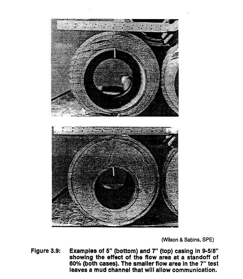
may even embed or bury into the wall of the formation. When casing contacts the wall, the drilling mud cake and some whole mud is trapped between the casing and the rock. This mud cannot be removed. Mud removal attempts by flushes and turbulent cement flow will have little contact as shown in the velocity profile sketches of Figure 3.8 and the photographs of mud displacement and channels created in a flow study recorded in Figure 3.9. Cement bypasses the mud and channels are left behind the pipe. These channels may completely undermine the principles of zone separation by cement and usually require repair by squeeze cementing. Channels are the most common form of primary cement
failure. Centralizers and pipe movement can improve the wall of the hole so that cement may more evenly displace the mud and completely fill the annulus. The design of centralizers varies widely with the application. Centralizing casing in nearly straight
holes is relatively easy, but as holes become more deviated, centralization becomes more difficult. In the more deviated wells, the weight of the casing will flatten most spring centralizers and may deeply embed some of the solid fin body units. The actual number of centralizers needed for a well depends on the acceptable deflection of the pipe and the severity of dog legs in the well. Examples of centralizers and their spacing are shown in Figure 3.10. Note in the examples that the centralizer spacing

decreases (more centralizers needed) as hole angle, pipe size and clearance increase.'^^^ The spacing is usually calculated by computer using a model such as that of Lee et al.27 These programs project spacing on the input of depth, dogleg severity, lateral load, tension and deviation. Typical spacing is from 30 to 60 ft between centralizers.
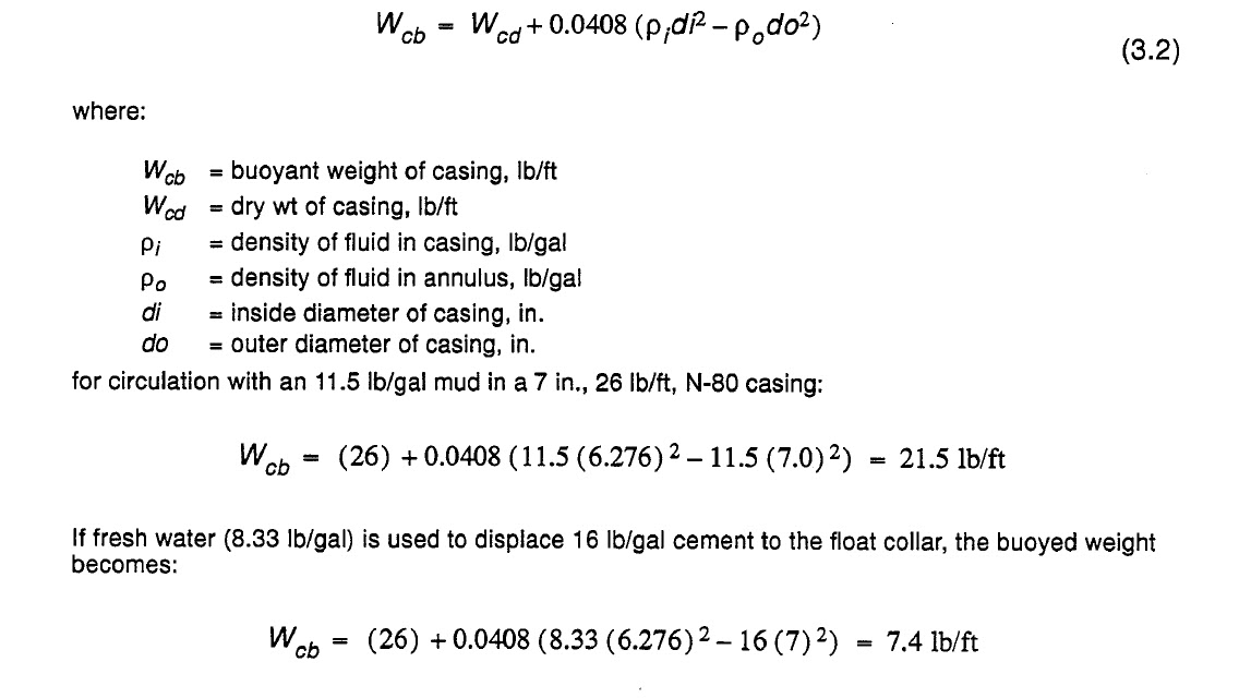
The variance in casing weight can be illustrated by the following examples of buoyed weight of casing.

Mud retards (slows) the set of cement. Minimizing this effect requires mud removal and separation from the cement whenever possible. Most casing strings are run full of mud during casing placement for assistance in well control. Cement displaces the mud from the casing before it flows up the annulus. If the mud is lighter than the cement or the mud has high gel strength, the cement will tend to finger or channel through the mud during its trip down the casing, mixing cement with mud. Mixing of mud and cement in the tubulars can be prevented by use of the two plug system. Before the cement is circulated down the well, a hollow rubber plug (Figure 3.11), with a disk that can be ruptured at high
pressure, is placed in front of the cement. The cement pushes this plug down to the bottom of the well, wiping the inside of the casing and displacing the mud from inside the casing ahead of the cement. At the bottom of the well, the plug “lands’t or is “bumped” and pressure builds up, rupturing the disk. Cement comes through the plug and can “turn” up the annulus. The second plug is dropped at the end of the calculated cement volume and the cement is displaced down the well with mud or water. The second plug, or top plug, is solid and has the same set of wipers as the first plug. At the bottom of the
hole, the top plug reaches the top of the first plug and pressure rises, indicating that the plug has been “bumped.” The plugs are made of drillable material that can be easily removed if the well is deepened. Correct loading of the plugs is critical. If the plug sequence is accidentally reversed and the top plug is dropped first, the job will “end when this solid plug hits bottom and the casing is left filled with cement. The actual displacement in the wellbore is very much different than the surface pump rate might indicate, especially when the density of the mud is much less than the density of the cement.*’ When a
lighter mud is displaced, the cement is in a “free fall.” The cement density is enough to rapidly push


the mud ahead and displace it from the well without the driving pressure of the pump. This is most noticeable in the later stages of the job during displacement when the casing contains more mud than cement. Surface pressure can go to almost zero at low injection rates (the well is said to go on ‘‘vacuum”). At this point, the well is taking fluid faster than it is being injected and mud return rate from the well can be more than the cement injection rate (a vacuum, with void space, is being created in the casing at the surface). As the cement turns the corner at the bottom of the well and starts up the annulus, the injection pressures caused by the heavier cement density will climb. The well returns, which
are monitored continuously at the surface, may go to zero as the cement fills the void volume in the pipe that was evacuated during free fall. It may appear that the well has lost returns by breaking down (fracturing) the formation. This rapid movement of fluids must be included in the design to allow control of the mud. The problems involved with free fall are rapidly increasing bottomhole pressure caused by resistance to faster than design mud flow rates around the shoe and an apparent “loss of  eturns,” as the cement fills the voids created during the initial free fall. An example of a field job showing
pump and return rates is shown in Figure 3.12.29 If, for example, the low rate of returns after 2 hrs, caused the operator to reduce the injection rate in an attempt to limit the apparent “loss” of cement, the cement would not be in turbulent flow and the mud cake might not be cleaned off the formation.16

After the plug has been bumped, the waiting-on-cement time, WOC, begins and pressure is held until cement has set. Pressure control is assisted by the float equipment. These devices are flapper or poppet valves near the bottom of the string that prevent the cement from returning to the casing. The oneway valves are of drillable material and are designed to stand the high velocity flow of large quantities of abrasive cement without damaging the sealing mechanism. Examples of the float valve are shown in Figure 3.13. If the float is at the end of the casing string, it is called float shoe. If it is placed a joint or two off bottom, then it is called a float collar. The preferred location will depend upon the operator
but for reasons of cement contamination control, float collars are usually preferred. The float collar results in a joint or two above the shoe being filled with the last cement pumped. This last cement may be contaminated with residual mud scraped from the casing wall by the top plug. Use of both a float collar and a float shoe are accepted practice in some areas. The dual floats are used as an extra barrier against pressure leak back. After WOC, drill bit just smaller than the casing id is then run if the well is to be deepened. The hole is drilled through the casing shoe and into the formation beneath this string. At this point, the casing
shoe is generally tested to insure that a good, leak-tight cement job has been obtained. If there are

leaks during this pressure test, the well is squeezed with cement until a pressure tight seal can be obtained. Since the casing shoe is the weak spot for blowout control, this step is a necessity. In summary, to properly place a good primary cement job requires several factors: selection of the right cement blend, the conditioning of mud, the removal of mud cake, centralization and movement of the pipe to insure full cement contact around the perimeter of the outside casing wall and use of enough cement to isolate the full zone.

Chapter 2: Casing Design con't lec (10 )


Cementing

Cementing a liner in place requires very closely controlled application of existing technology4s46 and a fair amount of risk. Three cementing methods are generally accepted for liners.47 Calculating the volume of cement to be used in a liner cementing job is extremely difficult and requires more information than available from a simple caliper run. For maximum caliper information, a four arm device capable of determining elliptical holes should be utilized for hole volume. Cement excesses of between 20% and 100% have been used on a number of liner jobs with larger excesses being responsible for better bonding and less channels. There is also a direct correlation with absence of channels and pipe movement. In liners of 500 ft or less, Bowman and Sherer4s46 recommend 100% excess
over the calculated annular volume and on liners of 3000 ft or more at least a 30% excess is recommended. A single-stage cementing job in which cement is circulated to the top of a liner; much like a


primary cement job and may include pipe movement during cementing. A planned squeeze program in which the lower part of the liner is cemented and the top part of the liner is squeezed later. This technique does not have good middle support and should not be used to isolate high pressure zones. The procedure is more widely followed in worldwide operations because of perceived problems of disengaging the liner running assembly from the liner and of flash setting of cement. Disengaging from the liner before cementing eliminates the ability to move the liner and almost universally results in poor cement jobs.
A third procedure commonly reserved for short liners is to fill part of the hole with cement and then slowly run the casing string into the cement, forcing the cement to flow up around the pipe. While this method can be accomplished with the minimum amount of pumping, the lack of circulation can result in poor removal of drilling mud. The technique is called a puddle job. Most liner jobs do not include plans to move the liner during the primary ~ e m e n t i n g .T~h~e ?re~as~o ns for this include:
1. Detaching the drill pipe from the liner before cementing minimizes the risk of being unable to detach from the liner once the cement is in place.
2. It may be necessary to change to a higher strength drillstring to allow pipe movement.
3. Movement may cause the liner hanger to become tangled with the centralizers near the top of the string.
4. Swab or surge pressures may be created during liner movement, especially in close tolerance wellbores.
5. Movement of the liner during cementing may knock off debris from the borehole wall. The debris may cause bridges and reduce the possibility of circulating cement. Despite the quoted disadvantages of staying attached during the cementing operation, Bowman and
Sherer4346 site several serious disadvantages with releasing the liner before cementing.

1. If the liner is hung off, the small bypass area around the liner offers a greater restriction to flow and causes more lost circulation because of the backpressure on the flowing cement.
2. If a downhole rotating liner hanger is used (rotation only), additional torque is required to initiate rotation to overcome bearing friction. Pipe often rotates easier when it is being raised or lowered. The difference in torque required is often substantial.
3. The potential for sloughing shale and annulus bridging is lessened when the operator can alternate between rotation and reciprocation.
4. Premature shearing of the pins in the liner-wiper plug is less likely because there is no relative movement between the liner and the setting tool (these two pieces of equipment move together). 49
5. If cement channels and there is a large hydrostatic pressure difference between inside and outside of the running tools, the cups or seals can give way before cementing of the liner is complete.
6. The displacement efficiency of cement around the tubulars when pipe is not moved is lessened. When liners are close clearance, then the density differences between mud and cement should be as close as possible. This negates the advantages of hole cleaning by higher density cement. Reciprocation4’ of the string is helpful because it produces lateral pipe movement that causes the pipe to change sides in the wellbore while it is alternately compressed and stretched (slacked off and picked up).43 R o t a t i ~ hnelp~s b~y ~mix~in~g th~e ~cem ent into wellbore irregularities and displacing mud due to drag forces produced by the flowing cement.43 Although liner movement should be a goal in any liner operation, well conditions may prevent any type of movement. In many cases, however, liner movement can be achieved in a well conditioned hole. Two clear cases where liner should not be moved are:43
1. When a short or small liner (3-1/2 in. or smaller) is run in a deep well, the liner should be hung off first since it may be impossible to tell from the weight indicator whether the liner had been released from the drill pipe.
2. In cases of hole deviation over 35O, reciprocation may be difficult due to high drag forces.
Many of the problems in liner running can be lessened by drilling a usable hole. Problems with keyseats, ledges, washouts, and other nongauge problems intensify when close tolerance liners are to be run. For additional information on problems involved in drilling a usable hole, refer to the chapter on Drilling The Pay.
When cement is circulated from the liner bottom to over the liner top, the cement must remain fluid long enough to detach from the liner and to circulate the cement from the well or to pull up above the top of the cement with the drillstring. If the cement flash sets, then the drillstring will become cemented in place and the hole most likely will be lost. Cement may prematurely set, thicken, or cement circulation may be lost for a number of reasons
1. Improper thickening or pump times caused by a poor design, ineffective field operations, or bad test results.
2. Poor density control on the cement or poor mixing of the cement at the surface. ,
3. Bridging in the annulus caused by a buildup of cuttings. This is caused typically by the increased number of particles picked up by higher annular velocities with a liner in the hole (due to its larger ID) than around the drillstring.
4. Plugging from dehydration of cement caused by excessive water loss in openhole sections below the overlap.
5. Increased hole cleaning of the cement as compared to4he drilling mud.
One of the most troublesome problems in cementing design is inadequate hole cleaning prior to cementing. This is especially true when light weight, low viscosity muds are used and little attention is paid to cuttings removal. Heaving shales are also a problem in hole fill and may cause washouts. Under no circumstances should circulation be halted with the liner in the hole before all of the cement has been displaced. Due to the small clearances and the yield point of cement, it may be very difficult to start circulation again.

Chapter 2: Casing Design con't lec ( 9 )

Casing String Design - Deviated Wells
The basic difference in casing design for a deviated well is the magnitude of the loads encountered in the deviated or angle build section. This requires bending and torque considerations. Greenip offers three major points for consideration:
1. Axial and torque loads can be estimated by analyzing separate sections.
2. Relationships can be developed for various parameters in casing string design.
3. The pickup, set down, and neutral states produce sufficiently different loads and magnitudes to analyze each separately.
First, divide the string into three segments, (1) the extension or reach interval, (2) the build interval (containing the deviation) and (3) the vertical interval, Figure 2.20. As with conventional casing design, the casing in a horizontal well is designed from the bottom up. Interval (2), the build interval, is simplified by assuming the angle is constant. Interval (l), the extension or reach portion is assumed to be a constant inclination. An example of the magnitude of the forces at pickup, neutral and set down are shown in Figure 2.21.


Liner Design

A liner is a casing string that does not extend back to surface. Liners may be permanent or temporary and run for a variety of reason^:^*^^^
1. Wear protection of the permanent casing string from rotating drill pipe or frequent tubing movement, especially in a deviated section.
2. Correction of hole difficulty such as doglegs, Key seats, or ledges.
3. Zone isolation of a high pressure zone or a lost circulation zone.
4. As an economical alternative to a full casing string.
5. To allow adequate room above the liner top for a large diameter pump.
6. To reduce casing tension loads in deep wells or to allow use of an available, low strength connection.
7. For repair of leaks or buckled casing.
8. For casing strengthening in earth shift zones.
Most reasons for liner design incorporate the cost reduction factor of not running casing back to surface. Liners have drawbacks as well, including several problems related to liner cementing. From a design standpoint, perhaps the biggest concern is that the intermediate string or the last full string becomes the top part of the liner and must handle the burst force generated by the zones crossed by the liner. Before a decision is made on use of a liner, the strength of the top part of the last full string must be checked against the new maximum expected surface pressure. Unless proven otherwise by cement bond evaluation tools, the upper pipe strength alone (no assistance from the cement sheath) must be capable of withstanding the pressure. If the upper section will not withstand the forces, it should be protected by running a full string, or, the string should be run before perforating the well.
The first approach liner design is the same as for full casing strings. The collapse, burst, and tension safety factors and design equations are the same. The basic differences between liner and casing design come to light in the design of liners for deep wells, hot  environments, and very high pressure zones.

Burst failure of liners is usually caused by kicks while drilling below a liner,39p40 pressure when fracture stimulating, or a tubing leak while producing a deep, high pressure zone. All these factors are made worse by a poor cement job. Since filling the casing/openhole annulus with cement significantly strengthens and supports the pipe, a good cement job over high pressure or earth movement zones is a requirement in any deep well.
An illustration of the complications caused by a poor cement job 39*40 is illustrated in Figure 2.22. After a primary cement job on the 9-5/8 in. string, the 6-518 in. liner is run and a circulation cement job is initiated. The low pressure zone at 13,800 breaks down while cementing, returns are lost and the cement top peaks at 13,400 (Figure 2.23a). A top squeeze with cement seals the top of the liner but leaves an uncemented zone from 13,120 ft to 13,400 ft (Figure 2.23b). While drilling near TD to test a deep structure, the temperature of the mud goes from 270" (temp. of the zone at 15,400 ft) to the bottomhole temperature (at 18,500 ft) of 345°F. Since both ends of the liner are cemented, stress will be induced by the temperature rise


Liner Tie-Backs

Although the liner completion described in Figure 2.22 may be used only as a liner, there are some conditions when the liner may be run back to surface. This liner tie-back may be temporary, to protect


permanent casing strings from wear during drilling4' or permanently, with cement, to strengthen the casing string through a high pressure zone or isolate and stop a casing leak38 or a leaking liner top.42 To allow a tie-back, most liners are equipped with a liner tie-back receptacle. The receptacle is an internally polished receiver that will accept the seal assembly of the tie-back liner. The tie-back liner usually incorporates some type of cement port or sliding sleeve and seat that will allow cement to be circulated through to the annulus and up the annulus to surface. The seat, float equipment andlor plugs used in the cementing operation are of drillable material.


Chapter 2: Casing Design con't lec ( 8 )


Casing String Design
A complex solution (API method) requiring computer solution is discussed first, followed by a practical, hand calculated method.

API Equations

Collapse strength rating is the external pressure required to collapse the casing. There are several methods for designing casing strings that will produce an acceptable casing design. Most methods use an x-diagram graphical approach or a calculated design based on a single strength concern in each area of design. The API procedure recognizes the changes in steel behavior in elastic, transition, plastic, and ultimate yield. The procedure illustrated here for determining the collapse strength is defined in API Bulletin 5C3.15 This casing design section is merely an introduction to the process. For a complete treatment, refer to Rabia's Fundamentals of Casing Design.14 When exposed to external pressure from mud or reservoir fluids and the effects of axial tension from the weight of the casing below any point (plus other loads)," a piece of casing may fail in one of three possible collapse  mechanisms: elastic collapse, plastic collapse, and failure by exceeding the ultimate
strength of the material. Each failure mode is bounded by limits of the ratio of casing diameter to thickness, plus a transition collapse formula was added arbitrarily since the API minimum elastic and rninimum plastic curves do not intersect. The transition formula covers this area. The API minimum collapse resistance equations are shown in Figure 2.12.15


Axial loads generally result from two forces:
1. hanging weight of the casing string
2. temperature induced forces in thermal wells and in nonthermal wells where operating temperatures may change by over 100°F.

Buoyancy


When the hole is filled with cement or mud, there is a buoyancy force exerted on the casing by the fluid in the hole and opposed by the fluid in the casing. Buoyant force acts on the entire casing string and results in a reduction in hanging weight. The amount of buoyant force exerted by the mud is equal . to the weight of the mud displaced by the submerged casing. The weight of steel at 489.5 Ib/ft3 or 65.4 Ib/gal, is several times the heaviest mud weight, yet the buoyant contribution of the mud is a significant factor in the hook load during running and cementing of the casing. Hook loads change dramatically during running and cementing operations and conditions do exist (running closed end casing, dry) where hook load could diminish to zero (the casing floats).
Buoyant weight, Wb, for an open-ended casing string of air weight W,, filled and surrounded by one fluid. is:


When the fluid in the casing is different from the fluid outside the casing, the volumes contained in the casing and displaced by the casing must be calculated and the weights summed against the air weight of the casing.
For the special case of an additional surface pressure such as holding pressure on the mud in the casing while cement sets in the annulus, the surface pressure is incorporated with the load produced by the mud. The buoyant force, FB, applied to the air weight of the casing becomes:


The pressure terms affect buoyancy much the same way as pressure affects tubing forces.

Collapse Design - Non-API Method

A practical method that considers burst, collapse, and tensile forces is also available. This method may be worked by equations or by graphical methods. The design is conservative in collapse resistance because of the basic assumptions of an empty string in a hole full of mud. In practice, most casing strings are filled with mud as they are run. The design begins at the bottom of the string. The collapse force produced by fluid pressure from a homogeneous fluid in the well and an empty casing string is:


resistance of the inner string. It may also be used in some casing designs. Because outside surface pressure is rare, the term is generally dropped.
It is customary to design the primary strings for the worst possible case. Since the worst possible case will be when the pipe is empty, the equation reduces to:


The outside surface pressure is assumed to be zero.
The design on an empty pipe string may seem excessive but it is done to eliminate consideration of triaxial forces produced by hole irregularities and other factors3 The worst possible case design, therefore, covers a multitude of other forces. Because of buoyancy produced by changes in axial load following setting of the cement, portions of the casing string may be in compression rather than tension. Casing above the point of zero axial tension has less collapse resistance, and casing below the point of zero axial tension has more collapse resistance since it is in compression. The collapse forces on a casing are usually visualized as being applied by the pressure of the mud in which the string is 
run. The effect of tension in reducing the collapse strength of the casing is generally considered, but the effects of ballooning, ovality, and temperature changes during circulating are often neglected. These effects can be severe, especially in high collapse resistance casing such as some 95-grades. For the burst calculations, one of two API approved formulas may be used. For plain end (nonthreaded) pipe and pipe with premium couplings (couplings stronger than the pipe body), Barrow's formula is used.


Burst force design may also be considered graphically, Figure 2.14.35 Eqn. 2.26 can be used to make the start of the X diagram of Figure 2.1 5. The X diagram is constructed
by collapse and burst c a l c ~ l a t i o n s . ’T~h~e ~m~a ximum burst line is drawn between the calculated burst at the surface and the calculated burst at the casing shoe. The collapse line is drawn between U and the maximum collapse pressure at the casing shoe, calculated by Eqn. 2.24 or 2.25. Tension design is the last step for each section of the casing string. The top of each section should be checked to see that the tensile ratings are not exceeded. The common safety factor is 1.6 to 1.8. When the tensile limits are exceeded, a change to a higher strength joint should be made. Tension limits may be gathered from a table of casing properties or calculated by dividing the API 5C3 value for joint strength by the safety factor

Chapter 2: Casing Design con't lec ( 7 )


Casing Weights and Grades
Common casing diameters range from less than 4-1/2 in. to over 20 in., and common tubing sizes are from 3/4 in. to over 4-1/2 in. In some high rate wells, tubing may be 5-1/2 in. to over 7 in. and 2-7/8 in. casing is run in tubingless completions. After the size is determined, the grade of the steel must be selected. The grades, along with weight, are based on pressure and corrosion requirements. The grades of steel used in oil industry tubulars
are shown in the following table for API and non-API sizes. The letters are assigned only to avoid confusion. Grades N-80 and stronger are considered high strength steels. Use of the higher strength steels increases cost and decreases resistance to some forms of corrosion. Use of the very hardalloys, such as V-150, makes packer setting difficult since the slips have difficulty setting in the very hard steel of the casing.


The yield and burst strength values for each casing size and weight are available from detailed tables are used for selection of casing once the necessary strength calculations are made. Often, because of economics or efforts to lighten the casing string, lower grade or lighter weight casing may be considered. Because the weight and pressure loads on a casing string change from top to bottom, a well designed string may incorporate several weights and grades of casing.


Casing Design Safety Factors

The design criteria for casing strings depends on the intended use and anticipated stresses. Because variance exists in both pipe manufacture and formation properties, safety factors must be incorporated into a design. The common ranges for safety factors in normal completion are shown b e l ~ w . ~ ~ ~ ~ Factors such as salt flows,7 very high pressures, sour service,8 reservoir compaction loads,g and thermal cycling'0 may change the safety factors.

tension                                               1.6 to 1.8
burst                                                 1.25 to 1.30
collapse                                            1 .O to 1.25


Earth shift forces, such as salt movement or other faulting and folding events caused by tectonic movement or are very difficult to address with a traditional safety factor. These forces have been successfully offset in some cases by designs using very heavy wall pipe or concentric pipe (casing cemented inside casing) over the affected zone. These types of casing designs are rare and most are generated by a series of trail and error approaches.

Load Description


The casing string must be designed for any load encountered from mud or reservoir fluids in placement or during any phase of stimulation or production. The common forces are tension during running, internal pressures during drilling, completion or production, and external pressures caused by drawdown, mechanical loads, and zone pressures. These loads are tension, burst, and collapse. The loads are often applied simultaneously in different parts of the string, and the forces may interact. The tension design of the casing string is made as if it were hanging free in air. A safety factor of 1.6 to 1.8 is applied to make allowances for a number of other tension factor^.^*^^'' These factors are briefly discussed in the following paragraphs. Collapse, burst, and tension forces are explained separately, but all must be satisfactorily accounted for in the final design. The design methods in this book result in a conservative design. Each design method is based on the worst possible case that could
occur during running. Collapse loading is force applied from outside the casing by either fluid pressure in a zone or earth shift forces. Forces from fluid pressure are collapse loadings while earth shift forces produce mechanical crush loadings. The largest collapse load from fluid pressure will usually be exhibited at the bottom of the string where hydrostatic pressure is greatest. The exception is an isolated, very high pressure zone. These zones are usually noted on the drilling record as places where kicks are taken.
The occurrence of earth shift zones from faults or salt movement are much harder to locate, especially on wildcats but may often show up on the drilling record as sticking points (not associated with mud cake buildup) or zones that have to be reamed or redrilled to get back to gauge hole size. The occurrence of salt zones are a very important tip to potential casing problem^.^ In one study area, 87% of the wells around a salt dome suffered some casing diameter reduction due to external, earth shift force.
’In the collapse design for fluid pressure, the worst case loading occurs with the unlikely combination of an empty casing string in a hole full of mud. A proper design, for effects of collapse only, would be a casing string that is strongest at the bottom and weakest at the top. Collapse is also affected by the effects of tension, which reduces the collapse rating or the “set depth limit” of the casing. As an object is pulled, it is more likely to lose diameter as it stretches in length. This thinning is a force in the same direction as collapse forces. Fortunately, the point at which the effect of tension induced “narrowing” of the string is at maximum is at the surface where effects of collapse pressure from hydrostatic pressure are the lowest. Burst pressure is a force applied from inside the casing by produced fluid pressures, hydrostatic mud load or addition of surface pressure during stimulation or workover operations. Since there is usually mud hydrostatic pressure along the outside of the casing before and during cementing, the net pressure or the difference between the pressure inside the casing and outside the casing will be used in the design of the casing. Unlike collapse, however, the shallower casing section is also important in the burst calculations from a safety standpoint. Burst pressures exerted by produced fluids are maximum at the surface (no offsetting hydrostatic load), while those exerted by mud is maximum at the bottom of the well. During fracturing, high burst loads may be exerted all along the string. Because collapse loads offset the burst load at the bottom of the string, the burst calculation is usually important above the “buoyancy neutral point.” This will be developed later. Tension is a force produced by the weight of the casing, the pressure differential, and the mud weights inside and outside the casing. It is largest at the top of the string and decreases with depth toward the bottom of the string. The tension load is partially offset by the buoyancy of the string in mud and is affected by pressure. When the pressure inside the tube rises, the pipe diameter is expanded and the length shortened or the tension is increased in a pipe that is anchored to prevent upward movement. When the pressure outside of a tube rises, the tube is elongated or the compression is increased if the
ends are fixed, Figure 2.6. Buckling failure in casing usually results from axial compression (lengthwise) overloading. The load produces ridges in the casing walls or corkscrewing of the tube. Either of these actions relieve compression, but the pipe is usually permanently yielded. The effects of buckling, Figure 2.7, is critical on the design of the casing string. The neutral point, Figure 2.8, is the dividing line between where buckling may occur and where it cannot occur in a tube that is evenly loaded around its radius. Above the neutral point, the tube is in tension and will not buckle. Below the neutral point, the upward buoyancy of the mud and other forces including pressure and mechanical loading place the tube in compression. Buckling can occur if the compressive load is more than the pipe can tolerate in the wellbore surroundings. The following information describes the neutral point, first in a theoretical manner and then in a practical way. There can be a neutral point in the casing or tubing string described by the formula:’*


When F, is algebraically greater than the right-hanc side of the equation, the pipe tends to be straldht. When F, is less than the equation, the pipe tends to buckle. When F, is equal to the equation, the neutral point is reached. The right-hand side of Eqn. (2.1) may also be referred to as the stability force. The true axial force will vary from point to point in the string, and will also vary over the life of the well. Typical considerations necessary to compute F, include the conditions at the time of cementing the casing or setting the packer in the case of tubing, as well as changes in the environment (temperature and pressure) to which the tubular is exposed. For casing, buckling primarily affects wear, particularly for intermediate strings through which additional drilling will occur. In extreme cases, splitting may
also be common. For tubing, the radial clearance between tubing and casing is usually sufficient to allow corkscrewing, often producing permanent deformation of the buckled portion of the string.

This equation is only appropriate for an open ended tube, clamped at both ends, with PO = 0 and AT = 0 , and ignoring weight. Under the unlikely conditions of a weightless string with no outside pressure, buckling in tension is possible. To illustrate the impact of Eqn. 2.2, consider a weightless tube that is open ended and subject to internal pressure only. For this loading, the only axial force is that due to ballooning given by Eqn. 2.2 and shown previously in Figure 2.6. As the inside pressure is increased, F, increases as 2pPjAis but the right hand side of Eqn. 2.1 increases as PjAi. The tube will not only buckle immediately, but will also buckle in tension.


Each zone or section of the casing string is checked for tensile requirements following collapse and burst calculations. In case of corrections made to a string design to compensate for tension load requirements, the order of selection is usually: (1) stronger connection, (2) higher grade (stronger steel), and (3) higher weight. Increasing connection strength and steel grade is preferred since they increase total string strength without adding significant weight. There are so many “premium” connections available that it is difficult to present a comprehensive data set. Tables of connection specifics are published yearly.37
For the sole purpose of casing collapse strength derating due to the effects of tension, a practical “buoyancy neutral point”, designated N.P., can be estimated by Eqn. (2.4) where:
The collapse resistance values given in the manufacturer tables are for casing that is not affected by axial load. In a well, the casing will be stressed by fluid pressures, Figure 2.9, mechanical bending forces, Figure 2.10, and tensile forces produced by the hanging weight of the casing. In collapse calculations, axial tension produces a reduction in collapse resistance. For purposes of this example, the axial tension is assumed to be from tension loads on a straight, free hanging pipe and not from bending loads.


Designing for forces involving earth shifts, highly deviated hole, sticking, reciprocating and rotating casing while cementing or running stresses, involves field optimization and the criteria for design differ from company to company. Earth shift design usually involves multiple strings of pipe or very heavy wall pipe across the problem zone. Problem zone recognition can often be made from drilling records where bit dragging (nonassociated with mud cake buildup) occurs long after a zone is drilled. Wells near salt domes or flows are considered likely prospects for formation movement.