Casing String Design
A complex solution (API method) requiring computer solution is discussed first, followed by a practical, hand calculated method.
API Equations
strength of the material. Each failure mode is bounded by limits of the ratio of casing diameter to thickness, plus a transition collapse formula was added arbitrarily since the API minimum elastic and rninimum plastic curves do not intersect. The transition formula covers this area. The API minimum collapse resistance equations are shown in Figure 2.12.15


Axial loads generally result from two forces:
1. hanging weight of the casing string
2. temperature induced forces in thermal wells and in nonthermal wells where operating temperatures may change by over 100°F.
Buoyancy
When the hole is filled with cement or mud, there is a buoyancy force exerted on the casing by the fluid in the hole and opposed by the fluid in the casing. Buoyant force acts on the entire casing string and results in a reduction in hanging weight. The amount of buoyant force exerted by the mud is equal . to the weight of the mud displaced by the submerged casing. The weight of steel at 489.5 Ib/ft3 or 65.4 Ib/gal, is several times the heaviest mud weight, yet the buoyant contribution of the mud is a significant factor in the hook load during running and cementing of the casing. Hook loads change dramatically during running and cementing operations and conditions do exist (running closed end casing, dry) where hook load could diminish to zero (the casing floats).
Buoyant weight, Wb, for an open-ended casing string of air weight W,, filled and surrounded by one fluid. is:

When the fluid in the casing is different from the fluid outside the casing, the volumes contained in the casing and displaced by the casing must be calculated and the weights summed against the air weight of the casing.
For the special case of an additional surface pressure such as holding pressure on the mud in the casing while cement sets in the annulus, the surface pressure is incorporated with the load produced by the mud. The buoyant force, FB, applied to the air weight of the casing becomes:


The pressure terms affect buoyancy much the same way as pressure affects tubing forces.
Collapse Design - Non-API Method
A practical method that considers burst, collapse, and tensile forces is also available. This method may be worked by equations or by graphical methods. The design is conservative in collapse resistance because of the basic assumptions of an empty string in a hole full of mud. In practice, most casing strings are filled with mud as they are run. The design begins at the bottom of the string. The collapse force produced by fluid pressure from a homogeneous fluid in the well and an empty casing string is:


resistance of the inner string. It may also be used in some casing designs. Because outside surface pressure is rare, the term is generally dropped.
It is customary to design the primary strings for the worst possible case. Since the worst possible case will be when the pipe is empty, the equation reduces to:
The outside surface pressure is assumed to be zero.
The design on an empty pipe string may seem excessive but it is done to eliminate consideration of triaxial forces produced by hole irregularities and other factors3 The worst possible case design, therefore, covers a multitude of other forces. Because of buoyancy produced by changes in axial load following setting of the cement, portions of the casing string may be in compression rather than tension. Casing above the point of zero axial tension has less collapse resistance, and casing below the point of zero axial tension has more collapse resistance since it is in compression. The collapse forces on a casing are usually visualized as being applied by the pressure of the mud in which the string is
run. The effect of tension in reducing the collapse strength of the casing is generally considered, but the effects of ballooning, ovality, and temperature changes during circulating are often neglected. These effects can be severe, especially in high collapse resistance casing such as some 95-grades. For the burst calculations, one of two API approved formulas may be used. For plain end (nonthreaded) pipe and pipe with premium couplings (couplings stronger than the pipe body), Barrow's formula is used.


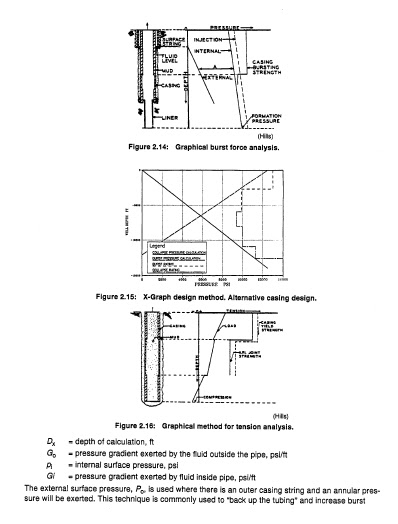
Burst force design may also be considered graphically, Figure 2.14.35 Eqn. 2.26 can be used to make the start of the X diagram of Figure 2.1 5. The X diagram is constructed
by collapse and burst c a l c ~ l a t i o n s . ’T~h~e ~m~a ximum burst line is drawn between the calculated burst at the surface and the calculated burst at the casing shoe. The collapse line is drawn between U and the maximum collapse pressure at the casing shoe, calculated by Eqn. 2.24 or 2.25. Tension design is the last step for each section of the casing string. The top of each section should be checked to see that the tensile ratings are not exceeded. The common safety factor is 1.6 to 1.8. When the tensile limits are exceeded, a change to a higher strength joint should be made. Tension limits may be gathered from a table of casing properties or calculated by dividing the API 5C3 value for joint strength by the safety factor
No comments:
Post a Comment