Showing posts with label Completion course. Show all posts

Completion Components lec ( 7 )

Introduction 

The selection of completion equipment and hardware is based on the reservoir,
field, wellbore and operational requirements that will achieve efficient, safe and
economic production.
There are many types of components available, each of which may be specified
in a number of service or dimensional variations, (e.g. H2S or normal service).
Principal completion components are categorized as follows:
  •  Production packers
  •  Gas lift equipment
  • Safety valves
  •  Tubing flow control equipment
  •  Permanent
  •  Retrievable
  •  Completion accessories

Production Packers 

The packer is often considered the most important downhole tool in the
production string. Completion packer types vary greatly and are typically
designed to meet specific wellbore or reservoir conditions, (e.g., single or
tandem packer configurations, with single, dual and triple completion strings).
Production packers can have several functions. However, the principal function
of a packer is to provide a means of sealing the tubing string from the casing or
liner. This seal must provide a long-term barrier compatible with reservoir
fluids or gasses and the wellbore annular fluid.
The production packer must also enable efficient flow from the producing (or
injection) formation to the tubing string or production conduit.

Downhole Anchor

 A secondary, but nonetheless important function of most packers is to provide
a downhole anchor for the tubing string. However, cup or isolation packers do
not anchor the tubing stringcontinued next However cup or isolation packers,
do not anchor the tubing string.

Subsurface Safety Valve

These hydraulically operated tubing flow control valves are used offshore, in
critical locations (next to a school or home) and areas of concern of the
environment, the reservoir, the facilities and the personel.

Gas Lift

Sidepocket mandrels with dummy valves are run in new free flowing completions
where workover costs are high and the reservoir will require artificial lift to
deplete.

Tubing Flow Control Equipment

This equipment expands the value of the completion by introducing flexibility.
Nipples, sleeves, plugs, chokes, test tools, standing valves, bomb hangers,
etc. could be utilized.


Casing String
Protection Example

For Casing
String Protection.


In most wellbores, the casing string or liner is a permanent component of the
completion system. Since casing replacement or repair procedures are
complicated and expensive, systems are designed (using packers) to protect
the casing from pressure differentials and corrosive conditions. The packer
and tubing string is typically easier to repair and/or replace than the casing
system.


Formation Safety
Control Example

For Downhole Formation
Safety Control


High Pressure gas and fluids are generally encountered at some depth. In the
absence of heavy completion fluids, a packer provides an effective means of
isolation. The high pressure can then be controlled by subsurface safety
valves in the tubing string attached to the packer. This also enables some
control of pressure on the wellhead. By inserting a tubing plug in the packer,
creating a temporary bridge plug, workover work above the packer can be
carried out with a greater degree of safety.


Multiple Zone
Completion Examples

For Zone Separation

 In multiple zone completions, it is generally necessary to separate the producing
zones for the following reasons:
  •  Legality - Government regulations monitor produced flow-rates as
allowable production. Often each production zone must be isolated,
which is more easily accomplished through the use of a packer.
  •  Control of formation fluids - Frequently, high and low pressure
zones are encountered. Packers are used to prevent cross flow of
reservoir fluids.


Artificial Lift Example
To Facilitate
Artificial Lift


When using gas lift to enhance production, a packer is utilized to separate
the produced fluid pathway from the injected gas pathway down the
annulus. Packers are often used with ESP’s to facilitate control of well zones.
Tubing anchors are commonly used to increase the efficiency of rod pumps.
Anti-rotational anchors are commonly used with progressive cavity pumps.


Remedial and
Repair Examples

To Facilitate
Remedial / Repair Work


In situations where casing is damaged, two packers can be used to seal off and
bypass the damaged area. With the use of accessory completion equipment,
such as stingers and on-off attachments, tubing can be pulled for repair and/or
replacement without releasing the packer.

Tubulars con't lec ( 6 )

High Strength
Tubing Failure

Failures of high-strength tubing are normally caused by:
  •  Manufacturing defects
  •  Handling/transportation damage
  •  Hydrogen embrittlement

API Tubing
Connections

There are two standard API coupling tubing connections available:


The API EUE type of connection is available in 23/8”, 27/8”, 31/2” and 41/2”.

Extra Clearance

 It is occasionally necessary to provide extra clearance to enable tubing
installation. To accommodate this, API couplings can be turned down (to
specified tolerances) without loss of joint strength. Special clearance collars
are usually marked with a black ring in the center of the color band indicating
steel grade. Extra-clearance, coupling-type thread forms have been developed
for non-upset tubing which have 100% joint strength.
Integral-joint premium threads provide additional clearance and are available
in a number of configurations. Some can be turned down to provide even
greater clearance. This type of joint is more expensive and is generally used in
special situations (high-pressure or gas well application).

Premium Tubing
Connections

In addition to the standard API connections, there are a wide variety of specific
joint connections available usually referred to as premium connection. Most
premium connections use a metal-to-metal seal which requires that the mating
pin and box surfaces are forced together with sufficient stress to establish a
bearing pressure greater than the differential pressure across the connection.
The bearing pressure (Pb) is defined as the pressure exerted between the metal
surfaces created by the torque used at make-up.
Premium connections are available in a wide variety of types, weights and
materials

Connection Seals

 Round thread connections form several metal-to-metal seals between the tapered
portions of pin and box surfaces. The small void between the crest and root of
the mating threads must be filled with thread compound solids in order to
transmit adequate bearing pressure from one threaded surface to another.
Some connections (e.g., HYDRIL) have large smooth metal-to-metal
connections. The threads in this type of connection have a relatively large
clearance and do not act as seals. Threads like Armco Seal Lock have both a
sealing thread and a smooth metal scaling surface (Fig. 10). A Teflon ring is
used in some premium connections to provide a supplementary seal and provide
corrosion protection.
The stresses applied during make-up and subsequent service determine the
success of the connection seal. When compiling tubular make-up procedures
the minimum, optimum and maximum torque for each connection type must be
known.


Basic String Design
and Selection

When selecting completion components, consider the factors shown below.
This of course is in addition to the basic efficiency, safety and economic
requirements of all completions.
  •  Facilitate installation
  •  Optimize production
  •  Simplify maintenance
  •  Enable stimulation or workover
  •  Provide for contingency

Tubular
Design Factors

The basic string design and selection process should take into
account the following guidelines before detailed planning is begun:


Drift Inspection

 Before running in the hole, drift the tubing with an API drift mandrel to ensure
the internal clearance is within tolerance.
Handle all tubing (new, used or reconditioned) with thread protectors in place.
Do not remove the thread protectors until the tubing is ready to be stabbed.
High-strength tubing is particularly susceptible to damage caused by improper
shipping and handling practices.


Measurement


 When running tubing and completion components, careful measurement of
each joint or item is essential. Each measurement is recorded in a tally book
against the joint number which should be clearly marked on each joint. The
tape used is divided into feet and decimal fractions, (e.g., the reading for 20 ft.,
6 in., would be read as 20.5 ft.).
Tubing joints (and other string components) are measured from the box end to
the beginning of the threads on the pin end (not the end). Record completion
components on a separate sheet of the tally book. The length, OD, grade and
ID are listed as appropriate for each component.
When the grade and size of pipe has been chosen, details of the following
points should be made known to field personnel:
  •  Handling - Tubing, especially high grade tubing (P-105, etc.)
must be handled carefully without dropping, denting, or nicking.
  •  Torque - Too loose or too tight make-up on a joint connection
can result in failure.
  •  Record (Tally) keeping - Accurate measuring and recording of
tubulars and placement of downhole components is essential. A
packer accidentally placed below the perforated interval is a prime
example of mis-measuring or miscounting tubing joints.

Running the
Tubing String

NOTE: Use PPE equipment.

Tubulars lec ( 5 )

Introduction

The design of an efficient, safe and economical completion system is dependent
upon the acquisition of accurate data and the selection of appropriate
components. Since the ultimate success of the completion system is dependent
on its successful installation, the installation procedures should also be given
some consideration.
Completion designs will vary significantly with the variation of the following
reservoir and location characteristics:
  •  Gross production rate
  •  Well pressure and depth
  •  Formation properties
  •  Fluid properties
  •  Well location
  •  Existing stock

Completion Equipment
Selection

As with all downhole components, data on completion components must include
full details of dimensions, profiles and connections. This is a basic requirement
of all downhole equipment, but is of special significance in completion design
and installation since many future well service activities will require throughtubing
access.

Basic Dimensional Data


  •  Length (depth)
  •  ID/OD (internal & external diameters)
  •  Thread type

Tubular Components

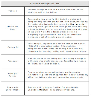
When completing a well, the proper selection of tubular components is possibly
one of the most important decisions. Tubular components come in a number of
different grades and diameters and several factors must be considered prior to
selection.
The higher formation pressures encountered in recent years requires tubing
and components have a greater yield strength. In addition, improved sealing
mechanisms at connections are also required. The types of connections
available have also increased. Those involved with completion design and
installation must understand the proper application of common tubing and
component types. Similarly, a good working knowledge of common seals and
connections is necessary.


Inspection Procedures


A critical part of any well completion operation is the inspection of components
prior to final assembly and installation. Completion specialists and supervisors
must be aware of necessary inspection procedures, as well as the basic handling
procedures for each completion component.

Tubing String
Specification

Tubing generally provides the primary conduit from the producing interval to
the wellhead production facilities. Therefore, the proper selection, design and
installation of tubing is a very important part of any completion system.


Tubing Length 

Tubing joints vary in length from 18 to 35 feet although the average tubing
joint is approximately 30 feet. In any tubing shipment the joint length will vary,
so accurate measurement of each joint is essential. Pup joints (for spacing out
the string) are available in shorter lengths (2’ - 20’) in 2’ increments.

Tubing Diameter

Tubing is available in a range of OD sizes. The most common sizes are 23/8", 27/8",
31/2" and 41/2" (51/2", 7" and 95/8" tubing is fairly common in some areas e.g., the
North Sea). The API defines tubing as pipe from 1" to 41/2" OD. Larger
diameter tubulars being termed casing (41/2" to 20").

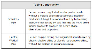
Tubing Construction 

Most types of tubing joint are threaded on each end (pin end) and connected
by couplings (box). The pipe used for production tubing may be manufactured
by one of two methods

Tubing Classification
Criteria

The following criteria are used to classify or specify tubing string material and
joint construction:


API Tubing Grades 

Much of the tubing used is manufactured according to API specifications and
must undergo a wide variety of tests and checks before shipment and
installation.
Standard API steel grades for tubing are J-55, C-75, L-80, C-95, N-80, P-105 and
V-150. Grades C-75, L-80 and C-95 are intended for hydrogen sulfide service
where higher strength than J-55 is required.
NOTE: L-80 may be 4130/4140 LHT material, 9Cr LHT, or 13Cr material.


Color Bands


The grade of new tubing can be identified by color bands:


High Strength
Tubing

High strength tubing is generally considered to include grades with a yield
strength above 80,000 psi. C-75, L-80 and N-80 are often included because
their as-manufactured yield strength often exceeds 80,000 psi. High strength
tubing, particularly P-105, presents an increased sensitivity to sharp notches
or cracks.
Any sharp-edged notch or crack in the surface of a material is a point of stress
concentration which tends to extend the crack progressively deeper into the
material, much like driving a wedge. Low strength materials are soft and ductile
and will yield plastically to relieve the stress concentration. High strength
materials do not yield to relieve the stress concentration and tend to fatigue or
fail more rapidly when subjected to cyclic stresses.

Maximum Allowable
Stress

Calculation of the maximum allowable stress of a certain pipe is carried out by
multiplying the minimum cross sectional area of the pipe, times the minimum
yield strength rating of the pipe


Well Completion Planning con't lec ( 4 )

Drilling

Drilling and associated operations, (e.g., cementing), performed in the pay
zone must be completed with extra vigilance. It is becoming increasingly
accepted that the prevention of formation damage is easier and much more
cost effective, than the cure. Fluids used to drill, cement or service the pay
zone should be closely scrutinized and selected to minimize the likelihood of
formation damage.

Evaluation

Similarly, the acquisition of accurate data relating to the pay zone is important.
The basis of several major decisions concerning the technical feasibility and
economic viability of possible completion systems will rest on the data obtained
at this time.

Pre-Completion

 A precompletion stimulation treatment is frequently conducted. This is often
part of the evaluation process in a test-treat-test program in which the response
of the reservoir formation to a stimulation treatment can be assessed..

Completion Assembly
and Installation


With all design data gathered and verified, the completion component selection,
assembly and installation process commences. This phase carries importance
since the overall efficiency of the completion system depends on proper
selection and installation of components.
A “visionary” approach is necessary since the influence of all factors must be
considered at this stage, i.e., factors resulting from previous operations or
events, plus an allowance, or contingency, for factors which are likely or liable
to affect the completion system performance in the future.
The correct assembly and installation of components in the wellbore is as
critical as the selection process by which they are chosen. This is typically a
time at which many people and resources are brought together. The demands
brought by high and mounting, daily charges imposes a sense of urgency
which requires the operation to be completed without delay. To ensure the
operation proceeds as planned, it is essential that detailed procedures are
prepared for each stage of the completion assembly and installation. The
complexity and detail of the procedure is largely dependent on the complexity
of the completion.

Primary Completion
Components
Primary completion components

 are considered essential for the completion to
function safely as designed. Such components include the safety valves, gas
lift equipment, tubing flow control tools and packers. In special applications,
(e.g., artificial lift), the components necessary to enable the completion system
to function as designed will normally be considered primary components.

Completion System 

Several types of devices, with varying degrees of importance, can be installed
to permit greater flexibility of the completion. While this is generally viewed as
beneficial, a complex completion will often be more vulnerable to problems or
failure, (e.g., due to leakage).
The desire for flexibility in a completion system stems from the changing
conditions over the lifetime of a well, field or reservoir. For example, as the
reservoir pressure depletes, gas injection via a side pocket mandrel may be
necessary to maintain optimized production levels. The selection of completion
components and fluids should reflect a balance between flexibility and simplicity.

Completion Assembly
and Installation Factors

Completion Fluids

A significant fluid sales and service industry has evolved around the provision
of completion fluids. Completion fluids often require special mixing and hauling
procedures, since (a) the level of quality control exercised on density and
cleanliness is high and (b) completion fluids are often formulated with
dangerous brines and inhibitors.

Initiating Flow

The process of initiating flow and establishing communication between the
reservoir and the wellbore is closely associated with perforating operations. If
the well is to be perforated overbalanced, (higher pressure in the wellbore than
in the formation) then the flow initiation and clean up program may be dealt
with in separate procedures. However, if the well is perforated in an
underbalanced condition, (lower pressure in the wellbore than in the formation)
the flow initiation and clean up procedures must commence immediately upon
perforation.Production Initiation


Underbalanced
Perforating

Perforating when the reservoir pressure is substantially higher than the wellbore
pressure is referred to as under-balanced perforating. While the reservoir/
wellbore pressure differential may be sufficient to provide an underbalance at
time of perforation, the reservoir pressure may be insufficient to cause the well
to flow after the pressure has equalized.
Adequate reservoir pressure must exist to displace the fluids from within the
production tubing if the well is to flow unaided. In the event the reservoir
pressure is insufficient to achieve this, measures must be taken to lighten the
fluid column typically by gas lifting or circulating a less dense fluid.
The flow rates and pressures used to exercise control during the clean up
period are intended to maximize the return of drilling or completion fluids and
debris. This controlled backflush of perforating debris or filtrate also enables
surface production facilities to reach stable conditions gradually.

Wellbore Clean Up

Wellbore cleanup is normally not required with new completions. However, in
wells which are to be re-perforated or in which a new pay zone is to be opened,
a well bore clean up treatment may be appropriate. There is a range of perforation
treatments associated with new or recompletion operations.

Overbalanced
Perforating

Perforating when the wellbore pressure is higher than the reservoir pressure is
referred to as Overbalanced Perforating. This is normally used as a method of
well control during perforating. The problem with this method is it introduces
wellbore fluid into the formation causing formation damage.
It is sometimes desirable to place acid across the interval to be perforated when
overbalanced perforating. The resulting inflow of acid results is a matrix type
acid treatment occurring.

Extreme Overbalance
Perforating

In this type of perforating operation the wellbore is pressured up to very high
pressures with gas (usually nitrogen). When the perforating guns are detonated
the inflow of high pressure gas into the formation results in a mini-frac, opening
up the formation to increase inflow.


Stimulation Treatments


Acid Washing
of Perforations


Perforation acid washing is an attempt to ensure that as many perforations as
possible are contributing to the flow from the reservoir. Rock compaction, mud
and cement filtrate and perforation debris have been identified as types of
damage which will limit the flow capacity of a perforation and therefore,
completion efficiency.
If the objective of the treatment is to remove damage in or around the
perforation, simply soaking acid across the interval is unlikely to be adequate.
The treatment fluid must penetrate and flow through the perforation to be
effective. In which case all the precautions associated with a matrix treatment
must be exercised to avoid causing further damage by inappropriate fluid
selection.

Hydraulic Fracturing


Hydraulic fracturing treatments provide a high conductivity channel through
any damaged area and extending into the reservoir. The natural fractures
within the formation material are opened up using hydraulic fluid pressure.
Commonly a proppont such as sand is introduced to ‘prop’ the fracture open
after the pressure is removed, but still will allow flow of reservoir fluids and
gases. Hydraulic fracturing treatments require a detailed design process which
is usually performed by the service supplier.

Well Service
and Maintenance
Requirements

The term “well servicing” is used (and misused) to describe a wide range of
activities including:
  •  Routine monitoring
  •  Wellhead and flowline servicing
  •  Minor workovers (through-tubing)
  •  Major workovers (tubing pulled)
  •  Emergency containment or response
Well service and maintenance preferences and requirements must be considered
during the completion design process. With more complex completion systems,
the availability and response of service and support systems must also be
considered.
Well bore geometry and completion dimensions determine the limitations of
conventional slick line, wireline, coiled tubing or snubbing services in any
application.

Logistic and
Location Constraints

Restraint imposed by logistic or location driven criteria often compromise the
basic cost effective requirement of a completion system. Special safety and
contingency precautions or facilities are associated with certain locations,
(e.g., offshore and subsea).

Logistic and
Location Criteria


Client Requirements


The completion configuration and design must ultimately meet all requirements
of the client. In many cases, these requirements may not be directly related to
the reservoir, well or location (technical factors). An awareness of these factors
and their interaction with other completion design factors can help save time
and effort in an expensive design process.
The following factors are common criteria which must be considered:
  •  Existing stock or contractual obligation
  •  Compatibility with existing downhole or wellhead components
  •  Client familiarity and acceptance
  •  Reliability and consequences of failure

Regulatory Requirements

There are several regulatory and safety requirements applicable to well
completion operations. These must satisfied during both the design and
execution phases of the completion process.
  •  Provision for well-pressure and fluid barriers
  •  Safety and operational standards
  •  Specifications, guidelines and recommendations
  •  Disposal requirements
  •  Emergency and contingency provision

Revenue and Costs

When completing an economic viability study, or comparison, the costs
associated with each of the following categories must be investigated.
  •  Production revenue
  •  Capital cost (including completion component and installation cost)
  •  Operating cost (including utilities and routine maintenance or
servicing cost, also workover, replacement or removal cost)
Installation costs are significant if special completion requirements impact the
overall drilling or completion time. The actual cost of completion components
is often relatively insignificant when viewed alongside the value of incremental
production from improved potential or increased uptime.


Economic Factors


A rudimentary understanding of the economic factors is beneficial.

  •  Market forces (including seasonal fluctuations and swing
production)
  •  Taxation (including tax liability or tax breaks)
  •  Investment availability


Company Objectives


A measure of success can only be made if there exists clearly stated objectives.
Such objectives may macroscopic, but nonetheless will influence the specific
objectives as applied to an individual well or completion. In addition, the wider
company objectives may allow clarification of other factors, (e.g., where two or
more options offer similar or equal benefit and no clear selection can be made
on a technical basis).

  •  Desired payback period
  •  Cash flow
  •  Recoverable reserves

Well Completion Planning lec ( 3 )

Introduction

Planning a completion, from concept through to installation, is a complex
process comprising many phases. Many factors must be considered, although
in most cases, a high proportion can be quickly resolved or disregarded.
Regardless of the completion design complexity, the basic requirements of any
completion must be kept in mind throughout the process. A completion system
must provide a means of oil or gas production (or injection) which is safe,
efficient, reliable and economical.
Ultimately, it is the predicted technical efficiency of a completion system, viewed
alongside the company objectives that will determine the configuration and
components to be used.

Completion
Planning Process


This section outlines the principal factors to be considered when planning an
oil or gas well completion. In addition to the technical influences on completion
design and selection, economic and non-technical issues are also detailed.
The relevance of these issues, in common with technical details, is dependent
upon the circumstances pertaining to the specific well, completion or field
being studied.
Although many wells (and fields) may be similar, the success of each completion
system is based on the individual requirements of each well. Therefore, it is
necessary to review and amend generic design or installation procedures as
required.

Principal Phases of
Well Completion Design


Impact of
Non-Optimized
Completions

The economic impact of designing and installing non-optimized completions
can be significant. Consequently, the importance of completing a thorough
design and engineering process must be stressed. Delaying the commencement
of the wells pay out period is one example of how non-optimized completion
design, or performance, can affect the achievement of objectives. However,
while reducing installation cost and expediting start-up are important objectives,
far-reaching objectives such as long-term profitability must not be ignored. As
illustrated, a more costly and complex completion may provide a greater return
over a longer period. In addition, the consequences of inappropriate design
can have a significant effect, (e.g., requiring premature installation of velocity
string or artificial lift).

Optimized Completion
System


Reservoir Parameters

The type of data outlined in this category are obtained by formation and
reservoir evaluation programs such as coring, testing and logging. Typically,
such data is integrated by reservoir engineers to compose a reservoir model.
The reservoir structure, continuity and production drive mechanism are
fundamental to the production process of any well. Frequently, assumptions
are made of these factors which later prove to be significant constraints on the
performance of the completion system selected.
Physical characteristics of the reservoir are generally more easily measured or
assessed. Pressure and temperature are the two parameters most frequently
used in describing reservoir and downhole conditions. The effects of
temperature and pressure on many other factors can be significant. For example,
corrosion rates, selection of elastomer or seal materials and the properties of
produced fluids are all affected by changing temperature and pressure.

Components of a
Reservoir Model


Produced Fluid
Characteristics

The ability of the reservoir fluid to flow through the completion tubulars and
equipment, including the wellhead and surface production facilities, must be
assessed. For example, as the temperature and pressure of the fluid changes,
the viscosity may rise or wax may be deposited. Both conditions may cause
unacceptable back-pressure, thereby dramatically reducing the efficiency of
the completion system.
Although the downhole conditions contributing to these factors may occur
over the lifetime of the well, they must be considered at the time the completion
components are being selected. Cost effective completion designs generally
utilize the minimum acceptable components of an appropriate material. In
many cases, reservoir and downhole conditions will change during the period
of production. The resulting possibility of rendering the completion design or
material unsuitable should be considered during the selection process.

Components of Produced
Fluid Characteristics

Wellbore Construction

The drilling program must be designed and completed with the scope and
limits determined by the completion design criteria.
Most obvious are the dimensional requirements determined by the selected
completion tubulars and components. For example, if a multiple string
completion is to be selected, an adequate size of production casing (and
consequently hole size) must be installed. Similarly, the wellbore deviation or
profile can have a significant impact.

Components of
Wellbore Construction


Introduction To Completions lec ( 2 )

Naturally Flowing Completions

Wells completed in reservoirs which are capable of producing without assistance
are typically more economic to produce. However, in high-temperature, highpressure
applications, a great deal of highly specialized engineering and design
work will be required to ensure that safety requirements are met.
In general, naturally flowing wells require less complex downhole components
and equipment. In addition, the long-term reliability and longevity of the
downhole components is generally better than that of pumped completions.
In many cases, wells may be flowed naturally during the initial phases of their
life, with some assistance provided by artificial lift methods as the reservoir is
depleted. Such considerations must be reviewed at the time of initial completion
to avoid unnecessary expense and interruption of production.

Artificial Lift Completions

All pumped, or artificially lifted, completions require the placement of
specialized downhole components. Such components are electrically or
mechanically operated, or are precision engineered devices. These features
often mean the longevity or reliable working life of an artificial lift completion
is limited. In addition, the maintenance or periodic workover requirements
will generally be greater than that of a naturally flowing completion.

Artificial Lift Methods

Pumped or assisted lift production methods currently in use include the
following:
  •  Gas lift
  •  Electric submersible pump
  •  Plunger lift
  •  Hydraulic or Jet Pump
  •  Variable Cavity Pump (VCP)
  •  Hydraulic or Jet pump
  •  Progressive cavity pump (PCP)


Single Zone Completion

 In single zone completions, it is relatively straight forward to produce and
control the interval of interest with the minimum of specialized wellbore or
surface equipment. Since typically one conduit or tubing string in involved,
the safety, installation and production requirements can be easily satisfied.
In most single zone completions, a packer (or isolation device) and tubing
string is used. This provides protection for the casing or liner strings and
allows the use of flow control devices to control production.
The complexity of the completion is determined by functional requirements
and economic viability. Several contingency features may be installed at a
relatively minor cost at the time of the initial installation. Consequently,
consideration must be given to such options during the initial design phase.

Multiple Zone Completions

Multiple zone completions are designed to produce more than one zone of
interest. However, there are many possible configurations of multiple zone
completion, some of which allow for selective, rather than simultaneous
production.


Phases of Well Completion

A sequential and logical approach to the design and execution process is
required. Since the ultimate efficiency of a completion is determined by
operations and procedures executed during almost every phase of a wells life,
a continual review and monitoring process is required. Typically this can be
summarized as follows:

Accurate Data is Essential

As in all design and execution processes, the acquisition of accurate or
representative data is essential. The level of accuracy required will vary with
the data type from the assumption of essential reservoir formation and fluid
properties to more general properties, which can more easily be measured.

Establish Objectives and Design Criteria

This initial phase may be summarized as the collection of data pertaining to
the reservoir, wellbore and production facility parameters. This data is
considered alongside constraints and limitations which may be technical or
non-technical in nature (e.g., company policy).
Some flexibility may be required, especially in exploration or development
wells, where there are several unknown or uncertain parameters.
The principal factors affecting the performance of any well relate to the three
areas illustrated in below. Of these, many of the fluid and reservoir properties
can be measured or inferred from measurements. Almost all elements of a
completion can be designed and an appropriate selection will thus affect well
performance.

Principal Factors Affecting a Well’s Performance


Pre-Completion: Constructing The Wellbore

The principal completion objectives of this phase include:

  •  Efficiently drill the formation while causing the minimum
practical near-wellbore damage

  •  Acquire wellbore survey and reservoir test data used to
identify completion design constraints

  •  Prepare the wellbore through the zone of interest for the
completion installation phase (run and cement production
casing or liner and preparation for sand control or
consolidation services)

Phase I: Design Objectives

The optim design is fundamental for the projected life of the well. The objectives
for which a completion system is designed vary. However, the following points
may be regarded as fundamental and will have some bearing in any application:

  •  Ensure the potential for optimum production (or injection)
  •  Provide for adequate monitoring or servicing
  •  Provide some flexibility for changing conditions or applications
  •  Contribute to efficient field/reservoir development and
production
  •  Ensure cost efficient installation and reliable operation

Phase II:
Completion Component
Selection and Installation

The proper selection and installation of completion components is required.
Components may be broadly categorized as follows:
In general, the optimum completion configuration (and system) will provide a
balance between flexibility and simplicity.

Phase III:
Initiating Production

In most cases, this phase of the completion process is further subdivided into
the following three stages:


 Phase IV:
Production Evaluation
and Monitoring

An initial production evaluation is necessary to confirm that the completion
system fulfills the production capabilities required by the design objectives.
Subsequent evaluation and monitoring exercises will provide the following
information on the reservoir, well and completion system:

  •  Statistics relating to the reliability and longevity of completion
components

  •  Verification that assumptions made during the design process
were accurate or representative

  •  Trends or statistical departures which may provide early
indication of completion problems or the need for intervention
or workover

  •  Periodic monitoring of reservoir parameters provides useful
data for the completion and production of offset wells or
recompletion as required by reservoir depletion


Introduction To Completions lec ( 1 )

Introduction

After a well has been drilled, it must be properly completed before it can be
put into production. A complex technology has evolved around the techniques
and equipment developed for this purpose. The selection of such equipment
and techniques should only be made following a thorough investigation of the
factors which are specific to the reservoir, well and production system under
study.

Three Basic Requirements
 
There are three basic requirements of any completion, in common with almost
every oil field product or service.

A completion system must provide a means of oil or gas production (or injection) which is:
 
  •  Safe
  •  Efficient / Economic
  •  Reliable 
Completion System Requirements

Current industry conditions may force operators to place undue emphasis on
the economic requirement of completions. However, a non-optimized system
may compromise long term company objectives. For example, if the company
objective is to maximize the recoverable reserves of a reservoir or field, a poor
or inappropriate completion design can seriously jeopardize achievement of
the objective as the reservoir becomes depleted.
In short, it is the technical efficiency of the entire completion system, viewed
alongside the specific company objectives, which ultimately determines the
completion configuration and equipment used.


Definition of Well Completion

Well completion involves a process which extends far beyond the installation
of wellbore tubulars and equipment. To highlight this fact, the following
definition of the term “completion” is presented:
  • Completion: The design, selection and installation of tubulars,
         tools and equipment located in the wellbore for the purpose of
         conveying, pumping or controlling production or injection fluids.

Under this definition, installing and cementing the production casing or liner,
as well as logging, perforating and testing, are part of the completion process.
In addition, complex wellhead equipment and processing or storage
requirements affect the production of a well and so may have some bearing on
the design and configuration of the completion.

History and Evolution of Oil and Gas Well Completions


As the understanding of reservoir and production performance has evolved,
then so too has the systems and techniques put in place as part of the completion
process.
Early wells were drilled in very shallow reservoirs which were sufficiently
consolidated to prevent caving. As deeper wells were drilled, the problems
associated with surface water prompted the use of a casing or conductor to
isolate water and prevent caving of the wellbore walls. Further development
of this process led to fully cased wellbores in which the interval of interest is
perforated.
Modern completions are now commonly undertaken in deep, hot and difficult
conditions. In all cases, achieving the completion and eventual production
objectives are a result of careful planning and preparation.

Completion Types
 
There are several ways of classifying or categorizing completion types. The
most common criteria for the classification of completions include the
following:

  • Wellbore/reservoir interface, i.e., open-hole or cased hole, horizontal completion
  •  Producing zones, i.e., single zone or multiple zone production
  •  Production method, i.e., natural flowing or  artifically induced production (Artificial Lift)
Open Hole or Barefoot Completions
Barefoot completions are only feasible in reservoirs with sufficient formation
strength to prevent caving or sloughing. In such completions there are no
means of selectively producing or isolating intervals within the reservoir or
open hole section. The production casing or liner is set and cemented in the
reservoir cap rock, leaving the wellbore through to the reservoir open.
The use of open hole completions is now restricted primarily to some types of
horizontal wells and to wells where formation damage from (air drilling) drilling
fluids is severe. To prevent an unstable formation from collapsing and plugging
the wellbore, slotted screen or perforated liners may be placed across the open
hole sections.

Example of Openhole Completions


Perforated Completions

The evolution and development of efficient and reliable perforating tools and
logging services has enabled complex completions to be designed with a high
degree of efficiency and confidence. Modern perforating charges and
techniques are designed to provide a clear perforation tunnel through the
damaged zone surrounding the wellbore. This provides access to the undamaged
formation, allowing the reservoir to be produced to its full capability.
Cased and cemented wells generally require less complex pressure control
procedures during the early stages of installing the completion components.
Efficient reservoir interpretation and appraisal techniques combined with a
high degree of depth control, enables selective perforating. This helps ensure
the successful completion and production of modern-day oil and gas wells by
precisely defining which zones of the reservoir will be opened for flow.
Multiple zone completions are often used in reservoirs with complex structures
and production characteristics. The ability to select and control the production
(or injection) of individual zones is often the key to ensuring the most efficient
production regime for the field or reservoir. Consequently, modern multiple
completions may be complex but maintain a high degree of flexibility and
control of production.

Examples of Cased Hole Completions


 continued