Open Hole Completions
The first decision on casing the pay zone is not of size or weight but whether or not to run casing at all. Open hole completions represent the simplest type of completions and have some very useful traits. They also present some problems. An open hole or barefoot completion is usually made by drilling to the top of the pay, then running and cementing casing. After these operations, the pay is drilled with a nondamaging fluid. Since the other formations are behind pipe, the drilling fluid overbalance is only that needed to control the reservoir pressure. This creates less damage. Open hole completions have the largest possible formation contact with the wellbore, allowing injection or production with every part of the contacted interval. The effect of the open hole on stimulated operations depends on the type of job. Fracturing operations are often easier in the open hole than through perforations by less possibility of perforation screenouts, but the perforations may make the zone easier to break down since a crack (the perforation) has already been placed. Matrix acidizing can more evenly contact the entire zone in an open hole but is more difficult to direct by straddle packer than in a cased hole. Hydraulic jetting is most effective in the open hole. Productivity of open hole gravel packs, especially the underreamed open holes are usually much higher than cased hole gravel packs. Why then, are casing strings even used? Part of the answer is in formation (wellbore) stability concerns and part is unfamiliarity with completing and producing the open hole completions. A decision must be reached on the merits of the completions on the pay in question. If the pay is prone to brittle
failures during production that leads to fill, most operators choose to case and cement. In areas of water coning or zone conformance problems, casing may make isolation of middle or top zones possible. With the advent of improved inflatable packers and matrix sealants, however, isolation is also possible in open holes, although wellbore diameter may be severely restricted.
Cased Hole Completions
A casing string is run to prevent the collapse of the wellbore and to act in concert with the cement sheath to isolate and separate the productive formations. The size of the casing is optimized on the expected productivity of the well and must be designed to withstand the internal and external pressures associated with completion, any corrosive influences, and the forces associated with running the casing.
An optimum design for a casing string is one designed from "the inside out", a design that is based on supplying a stable casing string of a size to optimize total fluid production over the life of the well (including possibility of secondary or tertiary floods). The effective design of a casing string for any well consists of four principal steps.
1. Determine the length and size of all casing strings that are needed to produce the well to its maximum potential.
2. Calculate the pressure and loads from predicted production and operations such as stimulation, thermal application and secondary recovery.
3. Determine any corrosive atmosphere that the casing string will be subjected to and either select alloys which can resist corrosion or design an alternate corrosion control system.
4. Determine the weight and grade of casing that will satisfactorily resist all of the mechanical, hydraulic, and chemical forces applied.
The sizing of a casing string must be complete before finalizing the bit program during the planning of the well. A casing string can be visualized as a very long telescoping tube with the surface casing or conductor pipe as the first segment and the deepest production string or liner as the smallest, most extended section. Each successive (deeper) segment of the casing string must pass through the last section with enough clearance to avoid sticking. Figure 2.1 illustrates the way the casing string fits together. The drill bits used for each section are usually 1.5 to 3 in. or more larger than the casing 0.d. to be run. When one section is cased and cemented, a bit just small enough to pass through the casing
drift ID is run to drill to the next casing seat (casing shoe set depth). During drilling, departing from the bit program is often required, especially in a wildcat when the fluid pressures in the formations cannot be controlled with a single mud weight without either breaking down some formations by hydraulic fracturing with the mud, or allowing input of fluid from other formations because of low hydrostatic drilling mud pressure (a kick). Ideally, just before this noncontrollable point is reached, the “casing point” is designated and a casing string is run. Economics of drilling and cementing dictate that these casing points be as far apart as formation pressures and hole stability will allow. Use of as few casing strings as possible also permits larger casing to be used across the production zone without
using extremely large diameter surface strings.

Use of small casing severely restricts the opportunities for deepening the well or using larger pumps. Use of small casing to save on drilling costs is usually a poor choice in any area in which high production rates (including water floods) are expected.
Description of Casing Strings
There are several different casing strings that are run during the completion of a well. These strings vary in design, material of construction and purpose. The following paragraphs are brief descriptions of the common required strings and specialty equipment.
The conductor pipe is the first casing which is run in the well. This casing is usually large diameter and may be set with the ”spudding” arm on the rig (The spudding arm drives in the casing.). The primary purpose of the conductor casing is as a flow line to allow mud to return to the pits and to stabilize the upper part of a hole that may be composed of loose soil. The depth of the conductor pipe is usually in the range of 50-250 ft with the depth set by surface rocks and soil behavior. It also provides a point for the installation of a blow-out preventer (BOP) or other type of diverter system. This allows any shallow
fluid flows to be diverted away from the rig, and is a necessary safety factor in almost all areas. In areas with very soft and unconsolidated sediments, a temporary outer string, called a stove pipe, may be driven into place to hold the sediment near the surface.
The well is drilled out from the conductor pipe to a depth below the shallow fresh water sands. The surface casing string is run through the conductor pipe and has three basic functions: (1) it protects shallow, fresh-water sands from contamination by drilling fluids, (2) prevents mud from being cut with brines or other water that may flow into the wellbore during drilling, and (3) it provides sufficient protection of the zone to avoid fracturing of the upper hole so that the drilling may proceed to the next casing point. This surface casing is cemented in place over the full length of the string and is the second line of safety for sealing the well and handling any high pressure flow. The intermediate string is the next string of casing, and it is usually in place and cemented before the higher mud weights are used. It allows control of the well if subsurface pressure higher than the mud
weight occurs and inflow of fluids is encountered. This inflow of well fluids during drilling or completion of the well is called a kick and may be extremely hazardous if the flowing fluids are flammable or contain hydrogen sulfide (sour gas). The intermediate casing may or may not be cemented in place and, if not cemented, may be removed from the well if an open-hole completion is desired. If a casing string is not hung from the surface, but rather hung from some point down hole, it is called a “liner”. In most wells, the top of the liner is cemented in place to provide sealing. The top of the liner is set inside an upper casing string. The section where the liner runs inside another string is the overlap
section. Production liners are permanent liners that are run through the productive interval. On some occasions] they may be run back to surface in a liner tieback operation. The tieback consists of a downhole mechanical sealing assembly in a hanger into which a linear string or the tie back string is “stabbed” to complete the seal. A cement job seals the liner into place in the casing and prevents leakage from the formation into the casing. The lower part of the casing string, into which the liner is cemented, is called the overlap section. Overlap length is usually only enough to insure a good seal, typically 300 to
500 ft. Overlap length may be longer where water or gas channeling would create a severe problem. Liners are run for a variety of reasons. If the operator wants to test a lower zone of dubious commercial quality, a liner can be set at less expense than a full casing string. Also, in lower pressure areas where multiple strings of pipe up to the surface are not necessary to control corrosion or pressure, the liner can be an expense-saving item. In wells that are to be pumped by ESP’s (Electric Submersible Pumps), the liner through the production section leaves full hole diameter in the casing string above the pay for setting large pumps and equipment. The production casing, or the final casing run into the well, is a string across the producing zone that is hung from the surface and may be completely cemented to the surface. This string must be able to withstand the full wellhead shutin pressure if the tubing or the packer fails. Also, it must contain the full bottomhole pressure and any mud or workover fluid kill weight when the tubing or packer is removed or replaced during workovers. The decision on whether to cement the full string is based on pressure
control, economics, corrosion problems, pollution possibilities and government regulations.
Casing Clearance
The necessary clearance between the outside of the casing and the drilled hole will depend on the hole and mud condition. In cases where mud conditioning is good or the mud is lightweight and the formations are competent, a clearance of 1.5 in. total diameter difference is acceptable. For this clearance to be usable, the casing string should be short. Primary cementing operations may not be successful in this clearance and cementing backpressures will be high. A better clearance for general purpose well completions is 2 to 3 in. For higher mud weights, poorer mud conditioning, poor quality hole and higher formation pressures, clearance should be increased. For more information on hole quality and sticking, review the chapter on Drilling the Pay. Excessive clearances should also be
avoided. If the annular area is too large, the cement cannot effectively displace the drilling mud.
A reference for hole size and casing size for single or multiple string operations are shown in
Figure 2.2.2 The solid lines indicate the common biffcasing combinations with adequate clearance for most operations. The dashed lines indicate less common (tighter) hole sizes or bitkasing combinations. Long runs of casing through close clearance holes usually leads to problems. Tight clearances should be avoided where possible.

Connections
The threaded connection of casing or tubing is important because of strength and sealing considerations. The connections are isolated pressure vessels that contain threads, seals and stop shoulder^.^ The fluid seal produced by a connection may be created in the threads by a pipe dope fluid or by a metal or elastomer seal within the connection. Strength of the connection may range from less than pipe body strength to tensile effciencies of over 11 5% of pipe body ~t rengthT.~hr eads are tapered and designed to fit a matching thread in a particular collar. In the API round thread series, the connection may be either short thread and coupling (ST&C) or long thread and coupling (LT&C) as illustrated in Figure 2.3. If the thread is an eight round, it means eight threads per inch. The length descriptionrefers to the relative length of the coupling and the amount of pipe that is threaded (the pin). Creation of a pressure tight seal with an API round thread requires filling the voids between the threads with a sealing compound (thread dope) during makeup of the joint.

Although the standard 8-round threaded connection is reasonably strong, it does not approach the strength of the body of the pipe. As tensile loads increase toward the limit of the pipe, the connection will normally fail by shearing off the threads from the pipe or by thread jumpout caused by pipe deformation under severe loads.
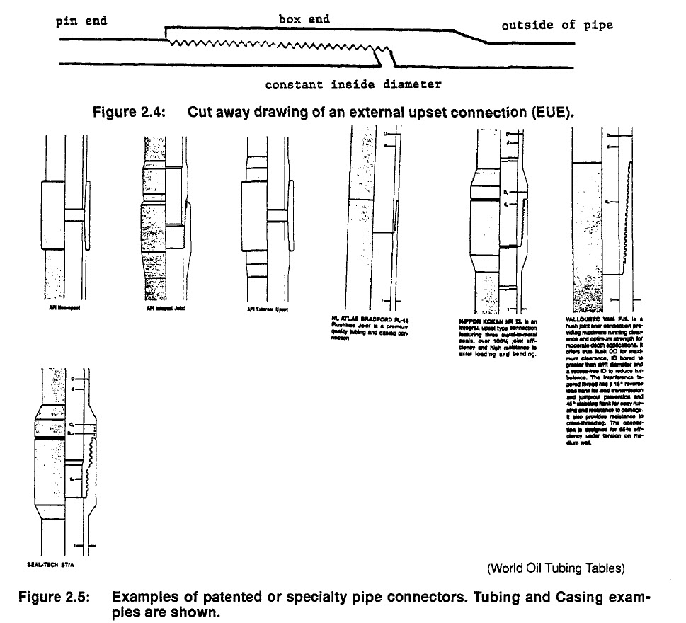
To make a stronger joint in tubing, a thicker (larger outside diameter) section is left at the end of the pipe so that threads can be cut without making the wall thickness of the pipe thinner than in the body. This form of connection is called external upset or EUE, Figure 2.4. Its inside diameter is the same as the pipe. A nonupset, or NU pipe and several other joint types are shown in Figure 2.5 The outside diameter of the EUE joint is larger than the NU connection, and the coupling or collar is normally manufactured on the pipe. Another method of increasing the strength of the threaded connection is by upsetting the connection to the inside of the pipe. This internal upset restricts the inside diameter of the pipe at every joint and is only used in drill pipe where a constant outside diameter is necessary.
Other sealing surfaces are available in special connections and have found popularity where rapidly made, leak free sealing is important. The two-step thread connection uses two sets of threads with a metal sealing surface between. In other connections, a groove at the base of the box may contain an elastomer seal. A variety of connection types and sealing surfaces are available, Figure 2.5. The disadvantage to the numerous thread and sealing combinations is that the connections cannot be mixed
in a string without crossovers (adaptors). A more detailed discussion of connections are available from other sources.
No comments:
Post a Comment