Auxiliary Completion Components
The production string is a receptacle for many kinds of flow control devices
and other accessories which are designed to increase the versatility of the
completion. Some of these devices are run as a part of the tubing string while
others are installed and retrieved by wireline or coiled tubing. Items installed
by wireline methods must have a facility in the tubing string which allows
removable devices to be located and secured.
Tubing Landing Devices
– Seating Nipples
– Seating Nipples
Seating nipples are landing devices which have a slightly restricted polished
ID which prevents tools from passing through and allow sealing of devices.
Seating nipples do not have a locking recess. The tool locates on the shoulder
of the reduced ID section and is held in place by pressure from above. The
standing valve is an example of a downhole tool often located in seating nipples.
These nipples are also commonly used to land recipricating rod pumps in.
Subsurface Safety Valves

Nipples
Tubing Landing Devices
– Profile Nipples
Nipples used to land downhole tools fitted with locking mechanisms are known
as profile nipples. In addition to an internal sealing surface, profile nipples
have a profiled locking recess.
There are two basic types of profile nipples, no-go nipples and selective nipples.
These nipples have a restricted ID, or a no-go shoulder at the bottom or top of
the seal surface, on which the downhole tool is located.
Selective nipples (Fig 6-1) can be placed in the tubing string at as many locations
as necessary. Selective nipples in a series can all have the same profile of
locking recess and ID. In this case, the specific nipple must be located by
determining its depth. This is the most common system. However, some
companies manufacture selective nipples with as many as six different profiles.
Such nipples may be run in a specific sequence with special keys conforming
to the position of the desired nipple. The keys on the running mandrel ensure
the device will only locate in the specific nipple desired. This system is not
commonly used anymore. There are several manufacturers of profile nipples,
each of which may have two or more product lines of profile nipples.
It is also possible for a variety of downhole tools to have a nipple profile cut
into them. These profiles may either be selective or no-go and receive a variety
of flow control devices.
Hydraulic Landing Nipples
For the installation of retrievable surface controlled subsurface safety valves
(SCSSV) that are actuated by hydraulic pressure, it has been necessary to
develop hydraulic landing nipples (Fig 6-3). Again, these nipples may be either
selective or no-go. They have two polished bores with a single port between
the bores for the introduction of hydraulic fluid under pressure.

Mandrels
Mandrels
Side Pocket
Side pocket mandrels (Fig 6-4) can also be considered landing devices. Most
side pocket mandrels provide an unrestricted flow path in the tubing string but
can receive a variety of different control devices. Side pocket mandrels have an
offset pocket next to the drift ID at the bottom of the mandrel containing a
polished bore for pressure sealing above and below a port. In addition to
landing gas lift valves, control devices as chemical injection valves, circulating
valves and circulating sleeves may be landed in side pocket mandrels.
A variety of devices for controlling communication between the tubing and the
annulus can be landed in side pocket mandrels. Gas lift valves can be set to
open at a preset pressure in response to either injection gas pressure or
production pressure. As soon as the valve opens, injection gas flows freely
into the fluids of the production conduit (either tubing or annulus, depending
on completion design.).
Mandrels
Conventional
Conventional
Conventional mandrels (Fig 6-5) are designed to carry and protect externally
mounted conventional gas lift valves. The internal surface of a conventional
mandrel does not have an upset area or pocket (as with a side pocket mandrel).
The flush internal surface is broken only by a small access port to the externally
mounted gas lift valve.
Down Hole Tubing
Hangers It is possible to land a section of tubing in a casing hanger nipple that was run
in with the casing. The casing hanger nipple has a no-go in it and is used to
land a tubing hanger attached to the tubing string. The tubing hanger sets in
the casing hanger nipple and supports the tubing. This capability is used
when the tubing may need to be separated above the tubing hanger utilizing a
separation device. The upper section of the tubing string may be pulled without
retrieving the entire string. The tubing string is also landed at the wellhead in
the tubing head. The tubing at the surface is attached to the tubing hanger,
which fits into the tubing head. The restricted ID of the tubing head holds the
slips of the tubing hanger.

Sleeves
Communication Devices Sliding Sleeve
A more efficient method of circulating between tubing and
annulus is to use a sliding sleeve (Fig 6-6) . This device is widely
used to permit circulation between the tubing and the annulus or
for selectively producing a zone. Sliding sleeves can be opened
using wireline methods by either a jar upward or downward with
a special shifting tool. Sliding sleeves have a large circulating
capacity and are excellent devices for communication between
the tubing and annulus for well kill or similar high fluid-volume
applications.
Other communication devices may be placed in side pocket mandrels to control
flow from the annulus to the tubing or vice versa. These circulating devices
include among others:
- Circulating sleeves
side pocket from damage due to the erosive effects of flow.
- Circulating valves
valves are designed for flow into the annulus while others are
designed to allow flow into the tubing.
- Dump-kill valves
predetermined pressure differential across the tubing before they
will open. Pins are sheared and fluids will flow under pressure
through the valve into the tubing. This device is placed relatively
deep in the well and is used to kill the well.
Tubing String
Protection Devices
Protection Devices
Types
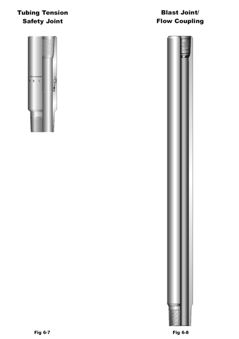
The production string is exposed to many physical forces which can cause
damage. Several devices and tools have been developed to protect the tubing
string and completion equipment from such forces or conditions.
- Safety joint (Fig 6-7)
becomes stuck, the safety joint can be separated. This enables a
heavier-fishing string containing jars to be used to retrieve the
stuck packer. Safety joints are available in straight pull or rotation
models.
- Flow coupling
in the tubing string to protect against erosion damage. Flow
couplings are normally available in lenghts betweeen 4 and 10
feet, and constructed from heavy walled pipe. These sections of
pipe serve to prevent fluid turbulence from eroding the tubing
string (Internal erosion).
- Blast joint (Fig 6-8)
between 2 and 20 feet. Blast joints are installed in the completion
string to withstand the scouring action of fluid flow from
perforations (External erosion).

Tubing Separation
Devices
Devices
Types
On - off tools (Fig 6-9)
If frequent removal of a portion of the tubing is expected during
the life of a well, tubing on-off attachments are available. These
attachments consist of a removable skirt section which is attached
to the tubing string, and a slick joint which usually contains a
wireline profile which stays attached to the packer.
Tubing Seal Receptacles (Fig 6-10)
Generally used in lengths of 10 to 30 ft., tubing seal receptacles
are installed immediately above the packer. These devices
resemble on-off connectors but have a much longer stroke, to
allow for tubing movement. The seal receptacle is normally run in
closed position either utilizing a ‘J’ or shear pins. Once landed
the receptacle skirt is released and spaced out on the slick joint
as required.
The slick joint generally incorporates a profile in the top. The
skirt assembly which contains the seals can be removed from the
slick joint and retrieved leaving the slick joint in place.

Tubing Expansion Devices
Expansion Joints
Under some conditions the tubing string of a producing well may be subjected
to large stress changes due to pressure or temperature changes These forces
cause the tubing string to expand and contract. If conditions warrant it, it may
be necessary to install an expansion device to avoid buckling or possible
separation of the tubing string. Expansion joints are designed to eliminate the
stress produced during these changes allowing the tubing string to expand
and contract without losing the integrity of the production string. They are
commonly produced in stroke lengths of 2 to 20 feet.
Non-splined expansion joints are free to rotate. No tubing torque can be
transmitted through this type of expansion joint.
Clutch type expansion joints (Fig 6-11) are free to rotate through most of their
stroke, but lock when fully extended or compressed to allow torque transmission
through the expansion joint.
Fully splined expansion joints (Fig 6-12) are locked against rotation throughout
their stroke.

Polished Bore
Receptacle (PBR)
Receptacle (PBR)
Available in lengths of 10 to 30 ft. long. PBR’s (Fig 6-13) consist of a polished
seal bore above the packer which is attached to the packer and a long seal
assembly which is attached to the tubing and seals into the polished bore. The
seal assembly is generally shear pinned into the seal bore when running. Once
landed the seal assembly is sheared and spaced out as required. The seal
assembly may be retrieved to be redressed or repaired. If it is necessary to
retrieve the polished seal bore it will require a second trip with a retrieving tool.
Seal Bore Extension (SBE)
A ‘SBE’ is run below a seal bore packer in order to extend the length of the
packer’s seal surface. Normally used in lengths of 10, 20, or 30 ft. long. An
extended locator type seal assembly is run into the seal bore and spaced out as
required.
Adjustable Union
An adjustable union (Fig 6-14) provides a means of spacing out and connecting
tubing on the short string side between dual packers. The adjustable union
may also be used space out production tubing near the surface.

The deisgn function of a subsurface safety valve is to prevent the uncontrolled
flow of well fluids.
Types
There are two major types of subsurface safety valves:
Subsurface Controlled Safety Valve (SSCSV)
This type of safety valve is controlled by well conditions. When
the downhole pressure or velocity reaches a predetermined
setting, the valve will close. The valves are actuated by the
ambient pressure differential created by increased fluid velocity
which occurs when the integrity of the production string above
the safety valve is broken. Subsurface controlled safety valves
are located in a profile nipple.
Surface Controlled Subsurface Safety Valve (SCSSV)
This type of safety valve is controlled by surface hydraulic
pressure transmitted through a small control line to control the
valve. Pressure is used to keep the valve open. If the control
pressure is released and the valve closes. SCSSVs shut off the
flow of the well completely, producing a pressure tight seal.
SCSSV’s may be tubing retrievable or wireline retrievable. The
tubing retrievable type can be pulled only with the removal of the
entire tubing string. Wireline retrievable valves that are controlled
from the surface must be landed in the hydraulic landing nipple
or inside of a locked out tubing retrievable safety valve.
SAtuaxnildiainrgy vCaolmvepletion Components
A standing valve functions as a downhole check valve. This valve allows flow
in one direction and may be landed in a seating nipple or landing nipple.
Pressure from below normally causes fluids to pass freely into the production
tubing while pressure from above results in the ball forming a seal in the seat.
Standing valves are normally run with an internal equalizing device which
allows the pressure to be equalized.
Pressure equalization is necessary before the standing valve can be removed
from the seating nipple. Standing valves are used primarily for setting hydraulicset
packers or for chamber lift applications.
Pump-out plugs
Pump-out plugs are often used when it is necessary to place a plug in the
tubing string below the packer. These one-time usage plugs, placed beneath
the packer, hold the pressure necessary for hydraulic-set packers to be set.
When pressure is increased to a specific preset value shear pins are sheared,
allowing the ball and sleeve to be forced down and out of the tubing. Once the
ball has been pumped out, the device can serve as wireline re-entry guide and
has a full open bore for the production of fluids. Pump-out plugs are normally
used only in the long string of dual completions, or in single string completions.
No comments:
Post a Comment