Directional Well Planning
About this Lecture
This chapter covers a number of topics which must be understood by the DD. The
various systems of coordinates used in the oilfield are discussed and compared. The
different survey calculation methods are described.
Understanding how a well plan (proposal) for a directional well is calculated is one of
the most important duties of the DD, particularly if he is working as an FSM or manager.
The basics of well planning are covered in this chapter.
One of the biggest mistakes a DD can make is to collide with another well. This chapter
describes the implications and dangers of kicking off close to other wells. The uses of
volume of uncertainty and traveling cylinder in anti-collision analysis are explained.
Although computer-based DD software is used to do (multiwell) anti-collision
calculations, the DD must understand what is actually being calculated. It is dangerous to
blindly accept the outputs from any computer program. It is advisable that the trainee DD
plot surveys by hand on the "Spider" plot in order to get familiar with anti-collision
techniques.
Objectives of this Chapter
On completing this chapter the directional driller should be able to do the following
exercise:
1. Describe the various systems of coordinates used in the oilfield.
2. List the various methods of calculating a directional survey.
3. Calculate a few surveys by hand (with a scientific calculator) using the Average
Angle method.
4. Explain what preliminary information for the directional well is needed from the
client.
5. Describe the effect on maximum angle of changing the kickoff point.
6. Explain the implications of high buildup and dropoff rates from a drilling standpoint.
7. Describe the four most common types of directional well profile.
8. Explain the principle behind the traveling cylinder method of anti-collision analysis.
9. Explain what is meant by Ellipse of Uncertainty.
3.1 Positioning and Coordinate Systems
Since the dawn of time, man has had to describe his location in one way or another. Just
as man evolved from relative to absolute positioning, the oil industry has evolved from
relative (i.e., the target is 1200' from the surface location along N 48.6° E) to absolute
(i.e., the target is located at UTM 6,234,345.67 m N and 474,628.34 m E). The need to
interchange meaningful data with others, government regulations, the requirement to
locate the blow out wellbore when the surface rig has cratered, and many other equally
important reasons require that the DD of today understand far more about positioning
and coordinate systems.
The problem
The earth is a sphere. Well, really it is an oblate spheroid (a squashed sphere). The radius
of the earth at the North pole is about 13 miles shorter than the radius at the Equator. If
the earth was the size of a billiard ball, the human eye could not tell the difference; but,
when it comes to modeling the size and shape of the border of a country or an oilfield
lease this 13 miles causes many problems for the geodesist ( a scientist who studies the
shape of the earth).
The maps and drawings used in directional drilling are flat. Plotting data which lies on
the surface or subsurface of a sphere onto a flat map is impossible without compromises
and the introduction of controlled error.
The science of geodesy and cartography (map making) are drawn upon heavily to
provide a complex, yet straight forward method for the DD to represent and plot his
surveys and wellplans.
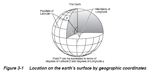
3.1.1 Geographic Coordinates (Latitude and Longitude)
To identify the location of points on the Earth, a graticule or network of longitude and
latitude lines has been superimposed on the surface. They are commonly referred to as
meridians and parallels, respectively. Given the North and South Poles, which are
approximately the ends of the axis about which the Earth rotates, and the Equator, an
imaginary line halfway between the two poles, the parallels of latitude are formed by
circles surrounding the Earth and in planes parallel with that of the Equator. If circles are
drawn equally spaced along the surface of the sphere, with 90 spaces from the Equator to
each pole, each space is called a degree of latitude. The circles are numbered from 0 at
the Equator to 90 North and South at the respective poles. Each degree is subdivided into
60 minutes and each minute into 60 seconds of arc.
Meridians of longitude are formed with a series of imaginary lines, all intersecting at
both the North and South Poles, and crossing each parallel of latitude at right angles, but
striking the Equator at various points. If the Equator is equally divided into 360 parts,
and a meridian passes through each mark, 360 degrees of longitude result. These degrees
are also divided into minutes and seconds. While the length of a degree of latitude is
always the same on a sphere, the lengths of degrees of longitude vary with the latitude
(see Figure 3-1). At the Equator on the sphere, they are the same length as the degree of
latitude, but elsewhere they are shorter.
There is only one location for the Equator and poles which serve as references for
counting degrees of latitude, but there is no natural origin from which to count degrees of
longitude, since all meridians are identical in shape and size. It, thus, becomes necessary
to choose arbitrarily one meridian as the starting point, or prime meridian. There have
been many prime meridians in the course of history, swayed by national pride and
international influence. Eighteenth-century maps of the American colonies often show
longitude from London or Philadelphia. During the 19th century, boundaries of new
States were described with longitudes west of a meridian through Washington, D.C.,
77°3'02.3" west of the Greenwich (England) Prime Meridian, which was increasingly
referenced on 19th century maps (Van Zandt, 1976, p. 3). In 1884, the International
Meridian Conference, meeting in Washington, agreed to adopt the "meridian passing
through the center of the transit instrument at the Observatory of Greenwich as the initial
meridian for longitude," resolving that "from this meridian longitude shall be counted in
two directions up to 180 degrees, east longitude being plus and west longitude minus"
(Brown, 1949, p. 297).
When constructing meridians on a map projection, the central meridian, usually a
straight line, is frequently taken to be the starting point or 0° longitude for calculation
purposes. When the map is completed with labels, the meridians are marked with respect
to the Greenwich Prime Meridian. The formulas in this bulletin are arranged so that
Greenwich longitude may be used directly.
The concept of latitudes and longitudes was originated early in recorded history by
Greek and Egyptian scientists, especially the Greek astronomer Hipparchus (2nd century,
B.C.). Claudius Ptolemy further formalized the concept (Brown, 1949, p. 50, 52,68).
Because calculations relating latitude and longitude to positions of points on a given map
can become quite involved, rectangular grids have been developed for the use of
surveyors. In this way, each point may be designated merely by its distance from two
perpendicular axes on the flat map.
3.1.2 Ellipsoid
An ellipsoid is the name of the volume obtained when an ellipse is rotated about one of
its axes. Specifically, an oblate spheroid is an ellipse rotated about the shorter
(semi-minor) axis. The oblate spheroid is the principal shape used in modeling the
surface of the earth.
The Earth is not an exact ellipsoid, and deviations from this shape are continually
evaluated. For map projections, however, the problem has been confined to selecting
constants for the ellipsoidal shape and size and has not generally been extended to
incorporating the much smaller deviations from this shape, except that different
reference ellipsoids are used for the mapping of different regions of the Earth.
There are over a dozen principal ellipsoids which are used by one or more countries. The
different dimensions do not only result from varying accuracy in the geodetic
measurements (the measurements of locations on the Earth), but the curvature of the
Earth's surface is not uniform due to irregularities in the gravity field. Until recently,
ellipsoids were only fitted to the Earth's shape over a particular country or continent. The
polar axis of the reference ellipsoid for such a region, therefore, normally does not
coincide with the axis of the actual Earth, although it is made parallel.
The same applies to the two equatorial planes. The discrepancy between centers is
usually a few hundred meters at most. Only satellite-determined coordinate systems, such
as the WGS 72, are considered geocentric. Ellipsoids for the latter systems represent the
entire Earth more accurately than ellipsoids determined from ground measurements, but
they do not generally give the “best fit" for a particular region.
3.1.3 Geodetic Datum
A geodetic datum is a definition of a model for the surface of the earth. They usually
consist of the definition of an ellipsoid, a definition of how the ellipsoid is oriented to the
earth's surface, a definition for the unit of length, an official name, and region(s) of the
earth's surface for which the datum is intended to be used. The reference ellipsoid is used
with an "initial point" of reference on the surface to produce a datum, the name given to
a smooth mathematical surface that closely fits the mean sea-level surface throughout the
area of interest. The “initial point” is assigned a latitude, longitude, and elevation above
the ellipsoid. Once a datum is adopted, it provides the surface to which ground control
measurements are referred. The latitude and longitude of all the control points in a given
area are then computed relative to the adopted ellipsoid and the adopted "initial point”.
The projection equations of large-scale maps must use the same ellipsoid parameters as
those used to define the local datum; otherwise, the projections will be inconsistent with
the ground control. The North American Datum 1927 (NAD27) is the most commonly
used datum for Canada, The U.S.A., and Mexico. European Datum 1950 (ED50) is the
most commonly used datum in the offshore North Sea. Geodetic datums are part
scientific and part political.
