Packers create a seal between the annulus and tubing. They may also serve as anchors and/or hangers for tubing strings. Although the concept of a packer is simple, the variety in devices is extensive. A packer may be described by its setting mechanism; hydraulic or mechanical, by its running mechanism; wireline or tubing, by its permeance; permanent or retrievable, by its function or by some other description. Its purpose is clear, it is the main downhole wellbore pressure control in many wells. Slips anchor the packer in place in the casing, a necessity where differential pressures exceed several thousand psi. Mechanical set packers set their slips by pushing a wedge- or cone-shaped piece against a set of tapered slips (hardened steel gripping surfaces) to drive the slips out and into the casing
wall. Mechanical energy is supplied by tubing rotation, tension, or compression. Hydraulic set packers set slips by fluid pressure, supplied by liquid or gas generating explosive charge. The slips are made on pistons that move out laterally for the few millimeters needed. The pistons may be designed to retract when pressure is released or remain out in some permanent installations. Packer slips are usually designed to hold in one direction, acting as an anchor to resist upward movement or as a hanger to resist downward movement. By using two sets of opposing slips, the packer can be anchored from either direction. An accompanying packing element (an elastomer, e.g., synthetic rubber)
is expanded by the slip setting action tubing or pressure which expands the seals against the wall of the pipe and generates a pressure tight seal.
The purposes of packers are:
1. Casing protection from pressure or fluids in the tubing
2. Separation of zones
3. Subsurface pressure and fluid control for safety
4. Artificial lift support equipment
Picking the right packer requires knowledge of the operational and completion requirements. This puts an early design load on completions/operational engineers: get it right or risk an early workover to replace a poorly selected packer.
Packers can be selected with aid of a decision tree planner such as shown in Figure 4.1. If a fully open wellbore is not required, the choice will most often be a permanent packer. As the name implies, the permanent packer is a permanent feature of the well. Removal requires milling of the slips.

Most valves work with the first tubing movement; opening a vent between upper and lower sections before the continued tubing movement releases the anchoring slips. When the tubing must be routinely pulled, a plug profile in the packer and an ON/OFF tool eliminates
killing the A wireline plug may be set in the profile in the packer to shut in the well and the tubing may be pulled while the retrievable packer remains in place with the well shut in. The well is effectively controlled by the packer and plug for repair or replacement of the tubing, without needing to kill the well. Various types of packers are schematically illustrated in Figure 4.2. The discussion that follows describes several of the features3-’
Solid head retrievable tension packers are used when the pressure below the packer is greater than the annulus pressure above the packer. This commonly occurs in an injection well or during low pressure treating. Tension packers are preferred in injection wells so that the slips are in the annulus: away from the corrosive effects of the injected fluid. Caution must be exercised when setting tension packers on small diameter tubing in a well with large diameter casing. In some cases, such as 2- 3/8 in. tubing in 7 in., casing the tension needed to set the packer may exceed the tensile strength of the tubing.8 When a force is applied to the tubing, it will respond by stretching. Figure 4.3 can be used to estimate stretch on tubing for an applied force. Solid head retrievable compression packers are used when pressure above the packer is greater than the pressure below the packer. This normally occurs in a producing well with a full annulus of packer
fluid. The compression set packers are the easiest to unseat and pull. Both compression set and tension set packers can be affected by tubing length changes caused by pressure fluctuations and temperature changes. Probably the most popular retrievable packers use a J-latch set with tubing rotation and slack off as the setting forces. When the tubing is latched in or otherwise solidly connected, careful consideration must be given to temperature effects to avoid cork screwing and buckling the tubing. Retrievable packers have a wide range of applications but are not used in deviated, thermal, or deep wells where tubing movement may be a severe problem. Retrievable hydraulic set packers are set by applying hydraulic pressure in the tubing. The pressure expands the elements and sets the slips against the wall of the casing. This packer may be removable and is usually released by pulling on the tubing which shears pins or opens a valve within the packer and releases the seals and slips. Hydraulic packers are very common in dual completions, especially in deviated wells.
Equipping a packer for the characteristics of an individual well is called “dressing” a packer. Most packers will work in a range of casing weights of a particular size casing.
As a check on BHT, use the following formula. Average temperature gradient is 1.6"F per every 100 ft of true vertical depth, d. The formula is BHT = T, + (0.1) (U) (1.6), where T, = average surface temperature OF. Gradients vary with geothermal activity. Substitute the local gradient for the 1.6 value. With the correct gradient values for individual areas, bottomhole temperature may vary by a factor of 2 for wells of the same depth but in different thermal activity areas. Changes in temperature are at least as important as the total temperature. The first change in temperature is experienced as the well warms up from a circulating BHT to the static BHT. Whenever the well is circulated with a cooler fluid, BHT decreases. The rate of warming after circulation is stopped, depends on the amount of temperature differential between the static and circulating BHT and the volume
of circulation that has occurred. Wells that have experienced long-term injection or circulation of cool fluids will reach static BHT much slower than wells in which the injection or circulation is limited. In general, the following statements describe how temperature affects the tubing or casing in a well.
1. The tubing temperature is assumed to be the same as the injected fluid if no circulation is
involved. If circulation occurs, the temperature of the top few tubing joints will be the same as the injected fluid, but the "temperature front" will only slowly work down. The analogy of heat transfer in a circulating well is that of a shell-and-tube heat exchanger. The fluid rising in the annulus exchanges heat with the injected fluid.
2. In injection without circulation, or in the case of produced fluids, assume the entire tubing string is the same temperature.
3. The temperature of an unheated injected fluid is assumed to be the same as the ambient air temperature in an onshore well. In offshore wells, injection of sea water from a deeply placed intake or injection of any fluid into a deep water well where the riser is not appreciably insulated can drastically lower the temperature. The coldest point in these systems is the mud line ternperature.
4. In a dual packer situation, treat each string as a separate calculation. The calculations on dual strings are made with the bottom string first, working up to the top.
The assumptions that all the tubing be considered as the same temperature is a simplifying move. It is a "worst possible case" that will result in a more conservative design (higher than needed safety factor). Where temperature alone affects the pipe, steel expands or contracts 0.0000828" per ft per O F gained or lost The extremes of temperature change in well completion and producing operations is usually seen in completions that are exposed to thermal stimulation or cyclic thermal production (or steam injection). The effect of tubing and casing length changes in the wells that are thermally cycled is covered in the chapter on thermal completions. Other severe cases of temperature cycling occur in a CO2-flood environment. In both injection and production wells, CO2 expansion may significantly reduce temperature.
Deep well operations pose special problems. In most deep well operations, the use of retrievable packers is extremely limited. Most operators choose to use a permanent packer for reasons of tubing movement (with a PBR) and with temperature and pressure limitations on some retrievables .


used to decrease damage from friction during stab-in


ling movement caused by differential pressure only when tubing pressure is greater than annulus pressure at the packer.
1. If there is no packer and the tubing is freely suspended (not touching the bottom of the well), all effects produce a length change.
2. If the tubing is landed on the packer, it is restrained from moving downward. Positive length changes cannot occur and are translated to force. Tubing shortening can occur.
3. If the tubing is latched into the packer, no movement can occur in either direction and all effects are converted to forces.
4. If the tubing is stung through the packer, all effects will be length changes unless the stop at the top of the seal assembly contacts the packer. If the tubing elongates enough to engage the stop, the movement will then be converted to force.
5. If the tubing is set in tension or compression, the effects of pressure or temperature induced force changes are added or subtracted from the force in place before the change. Sometimes these changes are enough to unseat the packer.
Example:
A well is completed with a PBR packer set at 9300 ft. and uses, 4-1/2 in., 12.6 Iblft, N-80
tubing. The tubing weight (compression) on the shoulder of the PBR is 20,000 Ib, at flowing conditions
of bottom hole flowing pressure of 1700 psi, and a surface pressure of 250 psi. The average
producing tubing temperature is 250" F. The average tubing injection temperature is 75°F. Use fracture pressures calculated in problem 2. What seal assembly length is needed to keep from pulling out of the PBR during a fracture stimulation? Assume that the seal assembly needs to be 1 ft longer than the length change from ballooning and temperature change. Consider both temperature and ballooning forces (ignore buckling and piston force). Seal assembly OD and ID are same as 4.5 in. tubing
(4.5 in. and 3.958 in. respectively).
Solution:
First, account for the 20,000 Ib force, DF , with temperature change =>
AF = 207 A, At
A, = cross sectional area of tubing wall, in2
At = change in average tubing temperature, OF
A, = n/4 (4.52 - 3.9582) = 3.6 in2
At = [20,000 / ((3.6) (207))l = 36.8 OF (this is the temperature change (cooling) in the tubing that is
required to remove the 20,000 psi of force load applied by the tubing at the packer. Remaining temperature
is (250 - 75) - 26.8 = 148.2"F.
Now, what length change will be produced with a temperature change (cooling) of 148.2OF?
AL = LCAt
L = length, inches
C = coefficient of thermal expansion, 6.9 x 1 0-6
At = change in average tubing temperature, OF
AL = (9300 x 12) (6.9 x 1 0-6) (1 48.2) = 11 4.24 inches = 9.51 ft
Ballooning Induced Pipe Length Movement
AL (-2L$E) [(APia-R2APoa)/(R2-1)]
E = modulus of elasticity, 30 x 106
L = length, inches
y = Poisson’s ratio, 0.3 for steel
R = ratio of tubing OD to ID
APia = change in average tubing pressure, psi
APoa = change in average annulus pressure, psi
AL = change in tubing length, in
tubing pressure before = (1700 + 250)/2 = 975 psi
tubing pressure after = (7836 + 4423)/2 = 61 30 psi
(the 7836 psi = BH frac pressure D hydrostatic back to packer, or
= [9600 ft x 0.83 psi/ft] D [(9600 - 9300) ft x 8.5 x 0.0521 = 7836 psi.
(the 4423 psi way surface pressure during fracturing).
APia = ?
APia = (6130 - 975) = 5155 psi
R = 433.958 = 1.1 37, R2 = 1.293
AL = (-2L$E) [(APia-R2APoa)/(R2-1)]
AL = (-2 (9300) (12) (0.3) / (30 X 1 06) ) [((5155 A ((1.293) (0))) / (1.293-l)]
AL = (-(0.002232)) (51 55 / 0.293) = 39.27 inches = 3.27 ft
The total length change = 9.51 + 3.27 = 12.78 ft
The stinger needs to be at least 12.8 + 1 ft = 13.8 ft long to keep the tubing from pulling out of the
packer during the fracture stimulation. A greater safety margin than 1 foot is common.

The effect of pressure in the annulus and in the tubing on the packer depends on the tubing/packer configuration. When the tubing id is larger than the bore of the packer, Figure 4.1 8, the annulus pressure pushes up and the tubing pressure pushes down. When the tubing id is smaller than the packer bore, Figure 4.19, the annulus pressure pushes down and the tubing pressure pushes up. The effect of pressure in this example is a piston effect.

In a sting through completion with a very short seal assembly or in a latch in completion, it is necessary to know how much weight to set off on the packer. Assuming the tubing id is smaller than the packer bore, the needed weight would be the product of the expected operating pressure times the difference in area between the tubing id and the packer bore.21 Packers are always tested for seal after setting. If the test pressure is too high, the packer can unseat and move. In a tension set packer, for example, the maximum annulus pressure for test can be calculated as follows.21 An injection well is equipped with a tension set, hook wall packer. The tubulars are 7 in., 23 Ib/ft, N-80,
(id = 6.366 in., Ai = 31.8 in.2) casing and the tubing is 2-7/8 in., 6.5 Ib/ft, C-75 (id = 2.041 in., Ai =
6.5 in.2) tubing. The packer is set with 18,000 psi Ib tension with the annulus filled with treated water
(density = 8.4 Ib/ft). The annulus pressure that can be applied before the packer releases is: (Remember that fluid pressures must account for the hydrostatic gradient.)
 In the surface pressure test, pressure up to 739 psi could be applied before the packer would unseat and move.
The combination of temperature and pressure effects on the length of the tubing produces a net change. The values from the previous four calculations are added to give a net movement or force. The stresses produced by pressure on the packer itself are also important and will determine if weight set or tension packers will become unseated under particular operating conditions. The pressure, either annulus or well pressure below the packer act on the exposed areas of the packer. The method of calculations of the packer forces is to sum the forces; upward acting forces are negative. There are
three forces that must be considered - (1) tubing weight or tension, (2) annular pressure force and (3) the pressure acting on the bottom of the packer. The annular pressure force is:


The piston force, previously described, is the net effect of the forces trying to push the seal into or out of the packer.
wall. Mechanical energy is supplied by tubing rotation, tension, or compression. Hydraulic set packers set slips by fluid pressure, supplied by liquid or gas generating explosive charge. The slips are made on pistons that move out laterally for the few millimeters needed. The pistons may be designed to retract when pressure is released or remain out in some permanent installations. Packer slips are usually designed to hold in one direction, acting as an anchor to resist upward movement or as a hanger to resist downward movement. By using two sets of opposing slips, the packer can be anchored from either direction. An accompanying packing element (an elastomer, e.g., synthetic rubber)
is expanded by the slip setting action tubing or pressure which expands the seals against the wall of the pipe and generates a pressure tight seal.
The purposes of packers are:
1. Casing protection from pressure or fluids in the tubing
2. Separation of zones
3. Subsurface pressure and fluid control for safety
4. Artificial lift support equipment
Picking the right packer requires knowledge of the operational and completion requirements. This puts an early design load on completions/operational engineers: get it right or risk an early workover to replace a poorly selected packer.
Packers can be selected with aid of a decision tree planner such as shown in Figure 4.1. If a fully open wellbore is not required, the choice will most often be a permanent packer. As the name implies, the permanent packer is a permanent feature of the well. Removal requires milling of the slips.
Production Packers
A gas well completion with a packer can often eliminate problems of produced liquid heading and loading if a tail pipe is run below the perforations. For some wells, including many older wells with increasing water cut and decreasing flowing tubing pressure and rate, smaller tubing or “velocity strings” can assist in keeping the gas velocity high enough to lift the liquids? Because the packer seals the tubing string, it must have compatibility with string size and string movement. The packer must be metallurgically compatible with produced fluids and the metal in the tubing string. Elastomers must be stable at operating temperatures, pressures and in produced fluids and completion or stimulation fluids.
Special Equipment
When large pressure differentials are expected in any tool that needs to be released, a pressure equalizing valve must be incorporated to keep the pressure from driving packer and tubing up (ordown) the well.
Most valves work with the first tubing movement; opening a vent between upper and lower sections before the continued tubing movement releases the anchoring slips. When the tubing must be routinely pulled, a plug profile in the packer and an ON/OFF tool eliminates
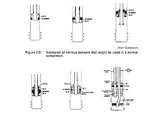
killing the A wireline plug may be set in the profile in the packer to shut in the well and the tubing may be pulled while the retrievable packer remains in place with the well shut in. The well is effectively controlled by the packer and plug for repair or replacement of the tubing, without needing to kill the well. Various types of packers are schematically illustrated in Figure 4.2. The discussion that follows describes several of the features3-’
Solid head retrievable tension packers are used when the pressure below the packer is greater than the annulus pressure above the packer. This commonly occurs in an injection well or during low pressure treating. Tension packers are preferred in injection wells so that the slips are in the annulus: away from the corrosive effects of the injected fluid. Caution must be exercised when setting tension packers on small diameter tubing in a well with large diameter casing. In some cases, such as 2- 3/8 in. tubing in 7 in., casing the tension needed to set the packer may exceed the tensile strength of the tubing.8 When a force is applied to the tubing, it will respond by stretching. Figure 4.3 can be used to estimate stretch on tubing for an applied force. Solid head retrievable compression packers are used when pressure above the packer is greater than the pressure below the packer. This normally occurs in a producing well with a full annulus of packer

fluid. The compression set packers are the easiest to unseat and pull. Both compression set and tension set packers can be affected by tubing length changes caused by pressure fluctuations and temperature changes. Probably the most popular retrievable packers use a J-latch set with tubing rotation and slack off as the setting forces. When the tubing is latched in or otherwise solidly connected, careful consideration must be given to temperature effects to avoid cork screwing and buckling the tubing. Retrievable packers have a wide range of applications but are not used in deviated, thermal, or deep wells where tubing movement may be a severe problem. Retrievable hydraulic set packers are set by applying hydraulic pressure in the tubing. The pressure expands the elements and sets the slips against the wall of the casing. This packer may be removable and is usually released by pulling on the tubing which shears pins or opens a valve within the packer and releases the seals and slips. Hydraulic packers are very common in dual completions, especially in deviated wells.
Dressing Packers
Equipping a packer for the characteristics of an individual well is called “dressing” a packer. Most packers will work in a range of casing weights of a particular size casing.
Allowing Tubing Movement
Polished seal bore packers are usually permanent packers set at a predetermined depth by either wireline or tubing. A seal assembly attached to the bottom of the tubing string is stung into the packer polish bore receptacle to achieve sealing. In wells with a severe amount of tubing movement, a long seal assembly and a polished seal bore packer are used to establish a slip joint to let the tubing expand and contract as needed
Effects of Temperature
Any well component will react to a change in temperature by a volume or reaction change. The components affected by temperature include tubulars, produced fluids, cements, acids, and corrosion properties. The changes in these fluids and materials, especially when the changes are unexpected, may lead to failures in components of the well. In most wells, a value for bottomhole temperature, BHT, is usually available from logging runs. As with most remotely sensed values, the BHT should be checked with other methods to make sure the value is correct. An incorrect BHT may lead to expensive problems with an otherwise correctly designed completion.As a check on BHT, use the following formula. Average temperature gradient is 1.6"F per every 100 ft of true vertical depth, d. The formula is BHT = T, + (0.1) (U) (1.6), where T, = average surface temperature OF. Gradients vary with geothermal activity. Substitute the local gradient for the 1.6 value. With the correct gradient values for individual areas, bottomhole temperature may vary by a factor of 2 for wells of the same depth but in different thermal activity areas. Changes in temperature are at least as important as the total temperature. The first change in temperature is experienced as the well warms up from a circulating BHT to the static BHT. Whenever the well is circulated with a cooler fluid, BHT decreases. The rate of warming after circulation is stopped, depends on the amount of temperature differential between the static and circulating BHT and the volume
of circulation that has occurred. Wells that have experienced long-term injection or circulation of cool fluids will reach static BHT much slower than wells in which the injection or circulation is limited. In general, the following statements describe how temperature affects the tubing or casing in a well.
1. The tubing temperature is assumed to be the same as the injected fluid if no circulation is
involved. If circulation occurs, the temperature of the top few tubing joints will be the same as the injected fluid, but the "temperature front" will only slowly work down. The analogy of heat transfer in a circulating well is that of a shell-and-tube heat exchanger. The fluid rising in the annulus exchanges heat with the injected fluid.
2. In injection without circulation, or in the case of produced fluids, assume the entire tubing string is the same temperature.
3. The temperature of an unheated injected fluid is assumed to be the same as the ambient air temperature in an onshore well. In offshore wells, injection of sea water from a deeply placed intake or injection of any fluid into a deep water well where the riser is not appreciably insulated can drastically lower the temperature. The coldest point in these systems is the mud line ternperature.
4. In a dual packer situation, treat each string as a separate calculation. The calculations on dual strings are made with the bottom string first, working up to the top.
The assumptions that all the tubing be considered as the same temperature is a simplifying move. It is a "worst possible case" that will result in a more conservative design (higher than needed safety factor). Where temperature alone affects the pipe, steel expands or contracts 0.0000828" per ft per O F gained or lost The extremes of temperature change in well completion and producing operations is usually seen in completions that are exposed to thermal stimulation or cyclic thermal production (or steam injection). The effect of tubing and casing length changes in the wells that are thermally cycled is covered in the chapter on thermal completions. Other severe cases of temperature cycling occur in a CO2-flood environment. In both injection and production wells, CO2 expansion may significantly reduce temperature.
Deep Completions


Seal Considerations
Successful seal selection involves specifying a seal that will operate at the production and treating conditions. The seal bore assembly may range from 1 to 3 ft in cool operations to over 30 ft in extreme cases of temperature ~y c l ing. ’S~e al materials such as those in Figure 4.15 are common in the industry. There are no universal elastomers (polymer, plastic, rubber, etc.) that are suitable for all uses. Seals must be selected on the basis of cost, thermal environment and chemical resistance. Seals may deteriorate by swelling, gas permeation, softening, hardening, nibbling under pressures, or failure of the internal bonding system that holds the elastomer compound together.21 Inserting the seal assembly on the tubing into the polished bore receptacle, is referred to as stab-in. It is the first and often the most severe task that a seal system must undergo.13 Damage caused by running may be overcome with a protective sleeve around the seals. Metal spacers between the seals areused to decrease damage from friction during stab-in


ling movement caused by differential pressure only when tubing pressure is greater than annulus pressure at the packer.
Length or Force Changes
Whether tubing length change or force change calculations are needed depends on how the tubing is attached to the packer.1. If there is no packer and the tubing is freely suspended (not touching the bottom of the well), all effects produce a length change.
2. If the tubing is landed on the packer, it is restrained from moving downward. Positive length changes cannot occur and are translated to force. Tubing shortening can occur.
3. If the tubing is latched into the packer, no movement can occur in either direction and all effects are converted to forces.
4. If the tubing is stung through the packer, all effects will be length changes unless the stop at the top of the seal assembly contacts the packer. If the tubing elongates enough to engage the stop, the movement will then be converted to force.
5. If the tubing is set in tension or compression, the effects of pressure or temperature induced force changes are added or subtracted from the force in place before the change. Sometimes these changes are enough to unseat the packer.
Example:
A well is completed with a PBR packer set at 9300 ft. and uses, 4-1/2 in., 12.6 Iblft, N-80
tubing. The tubing weight (compression) on the shoulder of the PBR is 20,000 Ib, at flowing conditions
of bottom hole flowing pressure of 1700 psi, and a surface pressure of 250 psi. The average
producing tubing temperature is 250" F. The average tubing injection temperature is 75°F. Use fracture pressures calculated in problem 2. What seal assembly length is needed to keep from pulling out of the PBR during a fracture stimulation? Assume that the seal assembly needs to be 1 ft longer than the length change from ballooning and temperature change. Consider both temperature and ballooning forces (ignore buckling and piston force). Seal assembly OD and ID are same as 4.5 in. tubing
(4.5 in. and 3.958 in. respectively).
Solution:
First, account for the 20,000 Ib force, DF , with temperature change =>
AF = 207 A, At
A, = cross sectional area of tubing wall, in2
At = change in average tubing temperature, OF
A, = n/4 (4.52 - 3.9582) = 3.6 in2
At = [20,000 / ((3.6) (207))l = 36.8 OF (this is the temperature change (cooling) in the tubing that is
required to remove the 20,000 psi of force load applied by the tubing at the packer. Remaining temperature
is (250 - 75) - 26.8 = 148.2"F.
Now, what length change will be produced with a temperature change (cooling) of 148.2OF?
AL = LCAt
L = length, inches
C = coefficient of thermal expansion, 6.9 x 1 0-6
At = change in average tubing temperature, OF
AL = (9300 x 12) (6.9 x 1 0-6) (1 48.2) = 11 4.24 inches = 9.51 ft
Ballooning Induced Pipe Length Movement
AL (-2L$E) [(APia-R2APoa)/(R2-1)]
E = modulus of elasticity, 30 x 106
L = length, inches
y = Poisson’s ratio, 0.3 for steel
R = ratio of tubing OD to ID
APia = change in average tubing pressure, psi
APoa = change in average annulus pressure, psi
AL = change in tubing length, in
tubing pressure before = (1700 + 250)/2 = 975 psi
tubing pressure after = (7836 + 4423)/2 = 61 30 psi
(the 7836 psi = BH frac pressure D hydrostatic back to packer, or
= [9600 ft x 0.83 psi/ft] D [(9600 - 9300) ft x 8.5 x 0.0521 = 7836 psi.
(the 4423 psi way surface pressure during fracturing).
APia = ?
APia = (6130 - 975) = 5155 psi
R = 433.958 = 1.1 37, R2 = 1.293
AL = (-2L$E) [(APia-R2APoa)/(R2-1)]
AL = (-2 (9300) (12) (0.3) / (30 X 1 06) ) [((5155 A ((1.293) (0))) / (1.293-l)]
AL = (-(0.002232)) (51 55 / 0.293) = 39.27 inches = 3.27 ft
The total length change = 9.51 + 3.27 = 12.78 ft
The stinger needs to be at least 12.8 + 1 ft = 13.8 ft long to keep the tubing from pulling out of the
packer during the fracture stimulation. A greater safety margin than 1 foot is common.
Setting the Packer
Successful packer setting depends on having a clean set point in the casing. Before a packer is set, a casing scraper, Figure 4.1 7, is run to remove mud, scale, cement, or corrosion debris and mill scale. Chances of successfully setting the packer go up sharply when a casing scraper is run. Some personnel resist running a scraper because of creating debris that can go to the perforated interval and cause formation damage.
The effect of pressure in the annulus and in the tubing on the packer depends on the tubing/packer configuration. When the tubing id is larger than the bore of the packer, Figure 4.1 8, the annulus pressure pushes up and the tubing pressure pushes down. When the tubing id is smaller than the packer bore, Figure 4.19, the annulus pressure pushes down and the tubing pressure pushes up. The effect of pressure in this example is a piston effect.

In a sting through completion with a very short seal assembly or in a latch in completion, it is necessary to know how much weight to set off on the packer. Assuming the tubing id is smaller than the packer bore, the needed weight would be the product of the expected operating pressure times the difference in area between the tubing id and the packer bore.21 Packers are always tested for seal after setting. If the test pressure is too high, the packer can unseat and move. In a tension set packer, for example, the maximum annulus pressure for test can be calculated as follows.21 An injection well is equipped with a tension set, hook wall packer. The tubulars are 7 in., 23 Ib/ft, N-80,
(id = 6.366 in., Ai = 31.8 in.2) casing and the tubing is 2-7/8 in., 6.5 Ib/ft, C-75 (id = 2.041 in., Ai =
6.5 in.2) tubing. The packer is set with 18,000 psi Ib tension with the annulus filled with treated water
(density = 8.4 Ib/ft). The annulus pressure that can be applied before the packer releases is: (Remember that fluid pressures must account for the hydrostatic gradient.)

Combined Forces
The combination of temperature and pressure effects on the length of the tubing produces a net change. The values from the previous four calculations are added to give a net movement or force. The stresses produced by pressure on the packer itself are also important and will determine if weight set or tension packers will become unseated under particular operating conditions. The pressure, either annulus or well pressure below the packer act on the exposed areas of the packer. The method of calculations of the packer forces is to sum the forces; upward acting forces are negative. There are
three forces that must be considered - (1) tubing weight or tension, (2) annular pressure force and (3) the pressure acting on the bottom of the packer. The annular pressure force is:


The piston force, previously described, is the net effect of the forces trying to push the seal into or out of the packer.
Special Packers
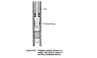
There are a number of packers that are made for special applications. Coiled tubing packers are available that will pass through 3-1/2 in. tubing and packoff in 7 in. casing.22 Inflatable packers are made that can be filled with cement for permanent repairs under partially collapsed casing, Figure 4.20.’ These packers are also used to packoff in openhole. Many packers are made of drillable materials that can be removed easier than the permanent packers that must be milled.23 This type of packer includes many of the cement retainers and squeeze tools.
Tubing Stretch and Compression
When packers are set by tension or weight of tubing, some deformation of the tubing is to be expected. Pulling force to set a tension set packer may stretch the tubing several feet depending on amount of pull and size of tubing. Figure 4.3 can be used to estimate the ~t r e t c hC.~o mpression set packers can result in tubing buckling and some steel compression. This accounts for a small amount of length and reduces the amount of weight that is set off on the packer.


