FUNCTIONS OF A DRILLING FLUID lec ( 1 )

There are a number of functions of a drilling fluid. The more basic of these are listed below:
1. Balance formation pressure
2. Carry cuttings and sloughings to the surface
3. Clean beneath the bit
4. Cool and lubricate bit and drill string
5. Seal permeable formations
6. Stabilize borehole
7. Corrosion control

In addition to these functions, there are several other functions with which the drilling fluid should not interfere:
1. Formation evaluation
2. Completion operations
3. Production operations

Clearly, these lists of functions indicate the complex nature of the Clearly, these lists of functions indicate the complex nature of the role of drilling fluids in the drilling operation. It is obvious that compromises will always be necessary when designing a fluid to carry out these functions, which in some cases require fluids of opposite properties. The most important functions in a particular drilling operation should be given the most weight in design of the drilling fluid.
Many of these functions are controlled by more than one mud property and should be discussed in more detail.

Pressure Control

 The density of drilling fluid must be such that the hydrostatic pressure exerted by the mud column will prevent flow into the wellbore. This is the first requirement of any drilling fluid and it must be provided for before considering any other mud property or function.
 The equation for calculating hydrostatic pressure is:
Hydrostatic Pressure, psi = (depth, ft.)(mud weight, lb./gal)(0.052) Pressure control would be rather simple if it consisted only of balancing the hydrostatic and formation pressures in the static condition. However, pressure is required to cause a fluid to flow This pressure is dissipated in frictional losses along the entire flow path.
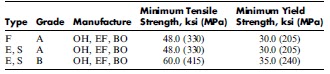
Consequently, the total pressure at any point in a circulating system is the sum of the hydrostatic pressure at that point and in the circulating pressure drop from that point to the exit point.
Under normal circulating conditions, the pressure at any given point in the hole is the sum of the hydrostatic pressure at that point and the circulating pressure drop from that point to the flow line. An example of circulating pressures at various points in the system is seen in
Figure 1.

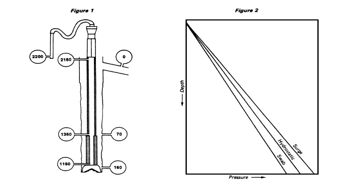
When pipe is run into the hole, the pipe displaces fluid, causing it to flow up the annulus. This is analogous to circulating the fluid and pressure calculations can be made in the same manner. When pipe is being pulled from the hole, the mud falls under its own weight to fill the void volume left by the pipe. The mud flowing down the annulus under gravity develops a flowing pressure drop that subtracts from the hydrostatic pressure. The total pressure at any point in the annulus is the hydrostatic minus the flowing pressure drop from the surface to that point in the annulus.

Figure 2

 illustrates pressure profiles under swab, static, or surge conditions. The difference in total pressure at any depth between the hydrostatic and swab or surge lines is the pressure drop caused by pipe movement.
Obviously, if a formation pressure is greater than the wellbore pressure under swab conditions, the formation fluid will flow into the well when the pipe is pulled. If the fracture pressure of a formation is less than the pressure at that depth under surge conditions, the
formation will be fractured while running the pipe and lost circulation will occur. These factors must be taken into account when establishing the required density of a mud.

Normally the mud density will be run slightly higher than required to balance the formation pressure under static conditions. This allows for a safety margin under static conditions and offsets the same amount of negative swab pressure. If the swab effect is still greater
than the overbalance, it must be reduced by slower pipe pulling speeds. This is necessary because further increases in mud density would cause problems in the areas of lost circulation, decreased penetration rates, and differential pressure sticking. The hole must
be filled when pulling pipe to replace the volume of the pipe.
Otherwise, the reduction in hydrostatic pressure will allow the well to flow.
By the same token, if the surge or the circulating pressure drop causes the total pressure to exceed the fracture pressure of a formation, the pipe running speed or the circulating rate must be decreased enough to prevent fracturing from occurring. When it becomes impossible to meet minimum and maximum pressure requirements at realistic pipe moving speeds or circulating rates, it is time to case the hole.
There are at least two different ways of calculating the annular pressure loss while circulating a mud. One method is to measure or predict the mud flow properties under downhole conditions and knowing the circulation rate and hydraulic diameter, calculate
directly the annular pressure drop.
This method has several weaknesses. First, an accurate knowledge of the flow properties of the mud is usually not available. This is especially true of water-base muds, which tend to gel with time when static in the hole and gradually decrease in viscosity when sheared. Such a mud may have a considerably higher gel strength and yield point initially after breaking circulation than under normal circulating conditions. Annular pressure drop calculations using flow line measurements of mud properties will yield pressure losses that
are less than actual when the mud is gelled downhole.
A second problem with annular pressure drop calculations is in knowing the hole diameter. If the hole is washed out, the pressure drop will be less than calculated; if a filter cake is deposited, the diameter will be decreased and the pressure drop greater than calculated. We are normally faced with estimating the average hole diameter in order to calculate pressure drop. The clearance between pipe and hole is very critical to pressure drop when this clearance is small. For this reason we need an accurate estimate of hole size around the drill collars. Fortunately, this is the part of the hole that should be least washed out and has the thinnest filter cake. A third factor that leads to inaccuracy in annular pressure drop
calculations is how well the pipe is centered in the hole. Our calculation procedure assumes perfect centering. This is usually not the case. The pressure drop in the annulus is greatest when the pipe is centered and is least when the pipe is lying against the wall.
This means that we tend to calculate a pressure drop which is higher than actual.
In general, this method of determining annular pressure loss is accurate for oil muds, which are not susceptible to temperature elation and which tend to keep the hole in gage. The method is not so accurate for water muds and especially for those which have high
gel strength at bottom hole temperature.
A second and more accurate method for determining annular pressure losses employs the use of an accurate standpipe pressure measurement. The pressure drop down the drill string and through the bit can be accurately calculated with a Reed Slide Rule and
subtracted from the standpipe pressure. The difference is the pressure drop up the annulus. This method is also quite useful while breaking circulation and until "bottoms up" has been obtained. During this period, the flow properties of the mud downhole are unknown and changing rapidly. This makes the direct calculation of annular pressure drop quite inaccurate. After breaking circulation, the annular pressure drop will decrease for a period of time. This is due to "shearing down" the gel structure of the mud. However, the shear rate in the annulus is not high  enough to break all flocculation bonds and the “bottoms up” mud will
remain abnormally high in viscosity. As this mud becomes cooler, as it is circulated up the hole, the viscosity will begin to increase. When the “bottoms up” mud is somewhere in the upper half of the hole, the pressure drop may begin increasing. If the circulation rate is not
decreased, a pressure drop greater than that required to initiate circulation may occur.
A detailed analysis of pressure drop calculations is given in Appendix A. Remember that these are calculations and the answers are only as good as the input data. Always try to determine how the most probable errors in the input data will affect your answer and how this will affect the drilling operation.

Hole Cleaning 

The ability to lift particles of various sizes out of the hole is one of
the most important functions of a drilling fluid. This is the only way
that the rock which is drilled or which sloughs from the wall is
carried out of the hole. In a 121/4-inch hole, about 130 pounds of
earth material must be removed for every foot of hole drilled. In fast
drilling an enormous amount of drilled cuttings are entering the mud
system. The mud circulation rate must be high enough to prevent an
excessive increase in mud density or viscosity.
Drilling a 12 ¼-inch hole at 3 feet per minute while circulating a 9
lb./gal mud at 10 bbl/min will result in a mud density increase in the
annulus to 9.5 lb./gal. If the drilled solids are fine and further
dispersed into the mud, a substantial increase in viscosity will result.
The combination of these two effects may cause the equivalent
circulating density of the mud in the annulus to exceed the fracture
gradient and cause loss of circulation. The circulation rate can be
increased to minimize the increase in density and viscosity due to
the influx of solids, but this will also cause an increase in equivalent
circulating density. If this ECD is also higher than fracture gradient,
then the drilling rate must be decreased.
It is possible, for short periods of time, to obtain such high drilling
rates in soft shales that cuttings cannot be wet and dispersed fast
enough to prevent them from sticking together and forming "balls" or
"slabs". For this reason, it is necessary to watch not only the long
time average drilling rate but also the instantaneous rates. A
procedure for calculating annular mud density increase due to drilled
solids influx is given in Appendix A.
Another, more common type of carrying capacity problem is the
ability of the fluid to lift the cuttings or sloughings and carry them out
of the hole. This problem is often difficult to detect because some of
the smaller cuttings come out while the larger ones remain in the
hole. If the hole is beginning to slough, the amount of shale coming
across the shaker will appear to be normal, but large amounts may
be collecting in the hole. Sometimes the appearance of the cuttings
will indicate poor hole cleaning. If the cuttings are rounded, it may
indicate that they have spent an undue amount of time in the hole.
The condition of the hole is usually the best indicator of hole
cleaning difficulty. Fill on bottom after a trip is an indicator of
inadequate cleaning. However, the absence of fill does not mean
that there is not a hole cleaning problem. Large amounts of cuttings
may be collecting in washed-out places in the hole. Drag while
pulling up to make a connection may also indicate inadequate hole
cleaning. When the pipe is moved upward, the swab effect may be
sufficient to dislodge cuttings packed into a washed-out section of
the hole. The sudden dumping of even a small amount of material is
often enough to cause severe drag or sticking.
Hole cleaning is a more severe problem in high-angle holes than in
vertical holes. It is not only more difficult to carry the cuttings out of
the hole, but they need to settle only to the low side of the hole
before causing problems. Consequently, more attention should be
paid to hole cleaning requirements in directional holes.
The ability of a fluid to lift a piece of rock is affected first by the
difference in density of they rock and the fluid. If there is no
difference in densities, the rock will be suspended in the fluid and
will move in a flow stream at the same velocity as the fluid. As the
density of the fluid is decreased, the weight of the rock in the fluid is
increased and it will tend to settle. The shear stress of the fluid
moving by the surface of the rock will tend to drag the rock with the
fluid. The velocity of the rock will be somewhat less than the velocity
of the fluid. The difference in velocities is usually referred to as a
slip velocity. The shear stress that is supplying the drag force is a
function of shear rate of the fluid at the surface of the rock and the
viscosity of the mud at this shear rate. A number of other factors
such as wall effects, inter-particle interference, and turbulent flow
around the particles make exact calculations of slip velocity
impossible. However, equations for estimating slip velocities are
shown in Appendix G. These equations give a rough idea of the size
range that can be lifted under a given set of conditions.
In general, hole cleaning ability is enhanced by the following:
1. Increased fluid density
2. Increased annular velocity
3. Increased YP or mud viscosity at annular shear rates.
It should be noted that with shear thinning fluids it is sometimes
possible to decrease annular velocity, increase the yield point, and
also increase the hole cleaning. This is done in order to minimize
hole erosion. Where viscosity is sufficient to clean the hole, the
annular velocity should be maintained below that for turbulent flow in
order to minimize annular pressure drop and hole erosion. This, of
course, is not possible when drilling with clear water where high
velocities and turbulent flow are usually necessary to clean the hole.
annular velocity should be maintained below that for turbulent flow in
order to minimize annular pressure drop and hole erosion. This, of
course, is not possible when drilling with clear water where high
velocities and turbulent flow are usually necessary to clean the hole.

Cleaning Beneath
the Bit

Cleaning beneath the bit appears to require mud properties almost
opposite from those required to lift cuttings from the hole. In this
case we want the mud to have as low a plastic viscosity as possible.
Since the fluid shear rates beneath the bit are at least 100-fold
greater than in the annulus, it is possible to have low viscosities at
the bit and sufficient viscosity in the annulus to clean the hole. A
mud that is highly shear-thinning will allow both functions to be
fulfilled. Flocculated mud and some polymer muds have this
characteristic.
Since cleaning beneath the bit relates to penetration rate, all other
factors that relate to penetration rate (such as density, hydraulics,
etc.) should be considered simultaneously.

Cooling and
Lubricating

Cooling and lubricating the bit and drill string are done automatically
by the mud and not because of some special design characteristic.
Muds have sufficient heat capacity and thermal conductivity to allow
heat to be picked up down hole, transported to the surface, and
dissipated to the atmosphere.

The process of
circulating cool mud
down the drill pipe
cools the bottom of the
hole. The heated mud
coming up the annulus
is hotter than the earth
temperature near the
surface and the mud
begins to heat the top
part of the hole. This
causes the
temperature profile of
the mud to be different
under static than
under circulating
conditions, as shown
in Figure 3.


The maximum mud temperature when circulating is cooler than the
geothermal bottom-hole temperature. The point of maximum
circulating temperature is not on bottom but about a third of the way
up the hole. These facts are important to remember when attempting
to predict mud behavior downhole. A mud additive which is not
completely stable at the geothermal bottom-hole temperature may
perform adequately at the circulating temperatures. If flocculation
due to temperature begins to occur during circulation, as evidenced
by increases in yield point and gel strength at the flow line, then we
can be assured that severe gelation will occur as the mud heats up
after circulation is stopped.
In addition to cooling the well bore, the circulating mud also removes
frictional heat and supplies a degree of lubrication. Cooling is
especially important at the bit where a large amount of heat is
generated. Sufficient circulation to keep the temperature below a
critical point is essential in using a diamond bit.
Lubrication is a very complex subject and especially as it applies to
the drilling operation. If a mud does not contain a great deal of
abrasive material such as sand, it will supply lubrication to the drill
string simply because it is a fluid that contains solids that are softer
than the pipe and casing. Attempts to improve this basic lubricating
quality of a mud are usually ineffective and expensive. Probably far
greater benefits can be realized by keeping the abrasive content of a
mud as low as possible.
Hole symptoms such as excessive torque and drag, which are often
associated with the need for a lubricant in the mud, are often caused
by other problems such as bit or stabilizer balling, key seats, and
poor hole cleaning. Sometimes materials sold as lubricants relieve
these symptoms, but not as cheaply or effectively as a more specific
solution to the problem.
The success or failure of a lubricant is related to its film strength in
relation to the contact pressure at the surface being lubricated. If the
lubricating film is "squeezed out", then the lubricant has apparently
failed. A material that appears to be a good lubricant in a test at low
contact pressure may fail in actual application due to higher contact
pressures, higher rotating speed, etc. The only good test of a
lubricant is under the exact conditions that exist where lubrication is
desired. Unfortunately, these conditions are not known downhole.
Lubrication should not be confused with attempts to reduce
differential pressure sticking. These are two different problems.
Additives sold as lubricants will probably do very little to relieve
differential pressure sticking if used in the concentrations
recommended for lubrication.


MATERIALS lec ( 3 )

1. INTRODUCTION
This chapter covers the most commonly used materials of construction
for piping systems within a process plant.
The two principal international codes used for the design and
construction of a process plant are ASME B31.3, Process Piping, and
the ASME Boiler and Pressure Vessel Code Sections.
Generally, only materials recognized by the American Society of
Mechanical Engineers (ASME) can be used as the ‘‘materials of
construction’’ for piping systems within process plants, because they
meet the requirements set out by a recognized materials testing body, like
the American Society of Testing and Materials (ASTM).
There are exceptions, however; the client or end user must be satisfied
that the non-ASTM materials offered are equal or superior to the ASTM
material specified for the project.
The Unified Numbering System (UNS) for identifying various alloys is
also quoted. This is not a specification, but in most cases, it can be crossreferenced
to a specific ASTM specification.
1.1. American Society of Testing and Materials
The American Society of Testing and Materials specifications
cover materials for many industries, and they are not restricted to the
process sector and associated industries. Therefore, many ASTM
specifications are not relevant to this book and will never be referred to
by the piping engineer.
We include passages from a number of the most commonly used
ASTM specifications. This gives the piping engineer an overview of the
specifications and scope in one book, rather than several ASTM books,
which carry specifications a piping engineer will never use.
It is essential that at the start of a project, the latest copies of all the
relevant codes and standards are available to the piping engineer.
All ASTM specification identifiers carry a prefix followed by a
sequential number and the year of issue; for example, A105/A105M-02,
Standard Specification for Carbon Steel Forgings for Piping Applications,
breaks down as follows:
A ¼ prefix.
105 ¼ sequential number.
M means that this specification carries metric units.
02 ¼ 2002, the year of the latest version.
Official title ¼ Standard Specification for Carbon Steel Forgings for Piping
Applications.
The complete range of ASTM prefixes are A, B, C, D, E, F, G, PS, WK;
however, the piping requirements referenced in ASME B31.3, which is
considered our design ‘‘bible,’’ call for only A, B, C, D, and E.
The requirements of an ASTM specification cover the following:
. Chemical requirements (the significant chemicals used in the production
and the volumes).
. Mechanical requirements (yield, tensile strength, elongation, hardness).
. Method of manufacture.
. Heat treatment.
. Weld repairs.
. Tolerances.
. Certification.
. Markings.
. Supplementary notes.
If a material satisfies an ASTM standard, then the various characteristics
of the material are known and the piping engineer can confidently use the
material in a design, because the allowable stresses and the strength of
the material can be predicted and its resistance against the corrosion
of the process is known.
1.2. Unified Numbering System
Alloy numbering systems vary greatly from one alloy group to the
next. To avoid confusion, the UNS for metals and alloys was developed.
The UNS number is not a specification, because it does not refer to the
method of manufacturing in which the material is supplied (e.g., pipe
bar, forging, casting, plate). The UNS indicates the chemical composition
of the material.
An outline of the organization of UNS designations follows:

In this chapter, the ASTM specification is the most common reference in
the design of process plants. Extracts from a number of the most
commonly used ASTM specifications are listed in the book, along
with the general scope of the specification and the mechanical
requirements.
For detailed information, the complete specification must be referred
to and the engineering company responsible for the design of the plant
must have copies of all codes and standards used as part of their
contractual obligation.
1.3. Manufacturer’s Standards
Several companies are responsible for inventing, developing, and
manufacturing special alloys, which have advanced characteristics that
allow them to be used at elevated temperatures, low temperatures, and in
highly corrosive process services. In many cases, these materials were
developed for the aerospace industry, and after successful application,
they are now used in other sectors.
Three examples of such companies are listed below:
. Haynes International, Inc.—high-performance nickel- and cobalt-based
alloys.
. Carpenter Technology Corporation—stainless steel and titanium.
. Sandvik—special alloys.
1.4. Metallic Material Equivalents
Some ASTM materials are compatible with specifications from other
countries, such as BS (Britain), AFNOR (France), DIN (Germany), and
JIS (Japan). If a specification from one of these other countries either
meets or is superior to the ASTM specification, then it is considered a
suitable alternative, if the project certifications are met.
1.5. Nonmetallic Materials
In many cases, nonmetallic materials have been developed by a major
manufacturer, such as Dow Chemical, ICI, or DuPont, which holds the
patent on the material. This material can officially be supplied only by
the patent owner or a licensed representative.
The patent owners are responsible for material specification, which
defines the chemical composition and associated mechanical characteristics.
Four examples of patented materials that are commonly used in
the process industry are as follows:
. Nylon, a polyamide, DuPont.
. Teflon, polytetrafluoroethylene, DuPont.
. PEEK, polyetheretherketone, ICI.
. Saran, polyvinylidene chloride, Dow.
Certain types of generic nonmetallic material covering may have several
patent owners; for example, patents for PVC (polyvinyl chloride) are
owned by Carina (Shell), Corvic (ICI), Vinoflex (BASF), and many
others. Each of these examples has unique characteristics that fall into
the range covered by the generic term PVC. To be sure of these
characteristics, it is important that a material data sheet (MDS) is
obtained from the manufacturer and this specification forms part of the
project documentation.
2. MATERIALS SPECIFICATIONS
Listed below are extracts from the most commonly used material
specifications referenced in ASME B31.3.
ASTM, A53/A53M-02 (Volume 01.01), Standard
Specification for Pipe, Steel, Black and Hot-
Dipped, Zinc-Coated, Welded and Seamless
Scope.
1.1 This specification covers seamless and welded black and hot-dipped
galvanized steel pipe in NPS 1⁄8 to NPS 26 (DN 6 to DN 650) for the
following types and grades:
1.2.1 Type F—furnace-butt welded, continuous welded Grade A.
1.2.2 Type E—electric-resistance welded, Grades A and B.
1.2.3 Type S—seamless, Grades A and B.
Referenced Documents
ASTM
A90/A90M, Test Method for Weight [Mass] of Coating on Iron and Steel
Articles with Zinc or Zinc-Alloy Coatings.
A370, Test Methods and Definitions for Mechanical Testing of Steel
Products.
A530/A530M, Specification for General Requirements for Specialized
Carbon and Alloy Steel Pipe.
A700, Practices for Packaging, Marking, and Loading Methods for Steel
Products for Domestic Shipment.
A751, Test Methods, Practices, and Terminology for Chemical Analysis of
Steel Products.
A865, Specification for Threaded Couplings, Steel, Black or Zinc-Coated
(Galvanized) Welded or Seamless, for Use in Steel Pipe Joints.
B6, Specification for Zinc.
E29, Practice for Using Significant Digits in Test Data to Determine
Conformance with Specifications.
E213, Practice for Ultrasonic Examination of Metal Pipe and Tubing.
E309, Practice for Eddy-Current Examination of Steel Tubular Products
Using Magnetic Saturation.
E570, Practice for Flux Leakage Examination of Ferromagnetic Steel
Tubular Products.
E1806, Practice for Sampling Steel and Iron for Determination of Chemical
Composition.
ASC Acredited Standards Committee X12.
ASME
B1.20.1, Pipe Threads, General Purpose.
B36.10, Welded and Seamless Wrought Steel Pipe.
Military Standard (MIL)
STD-129, Marking for Shipment and Storage.
STD-163, Steel Mill Products Preparation for Shipment and Storage.
Fed. Std. No. 123, Marking for Shipment (Civil Agencies).
Fed. Std. No. 183, Continuous Identification Marking of Iron and Steel
Products.
American Petroleum Institute (API)
5L, Specification for Line Pipe.
Methods of Manufacture. Open hearth (OH), electrofurnace (EF), basic
oxygen (BO).
Chemical Requirements. Refer to ASTM A53/A53M.
Mechanical Requirements. These are extracted from ASTM A53/A53M:


ASTM, A106-02a (Volume 1.01), Standard
Specification for Seamless Carbon Steel Pipe
for High-Temperature Service
Scope. This specification covers seamless carbon steel pipe for hightemperature
service (Note: It is suggested that consideration be given to
possible graphitization) in NPS 1⁄8 –NPS 48 inclusive, with nominal
(average) wall thickness as given in ANSI B 36.10. It is permissible to
furnish pipe having other dimensions provided such pipe complies with all
other requirements of this specification. Pipe ordered under this
specification is suitable for bending, flanging, and similar forming
operations and for welding.Whenthe steel is to be welded, it is presupposed
that a welding procedure suitable to the grade of steel and intended use or
service is utilized (Note: The purpose for which the pipe is to be used should
be stated in the order. Grade A rather than Grade B or Grade C is the
preferred grade for close coiling or cold bending. This note is not intended
to prohibit the cold bending of Grade B seamless pipe).
Referenced Documents
ASTM
A530/A530M, Specification for General Requirements for Specialized
Carbon and Alloy Steel Pipe.
E213, Practice for Ultrasonic Examination of Metal Pipe and Tubing.
E309, Practice for Eddy-Current Examination of Steel Tubular Products
Using Magnetic Saturation.
E381, Method of Macroetch Testing, Inspection, and Rating Steel Products,
Comprising Bars, Billets, Blooms, and Forgings.
A520, Specification for Supplementary Requirements for Seamless and
Electric-Resistance-Welded Carbon Steel Tubular Products for High-
Temperature Service Conforming to ISO Recommendations for Boiler
Construction.
E570, Practice for Flux Leakage Examination of Ferromagnetic Steel
Tubular Products.
ASME
B36.10, Welded and Seamless Wrought Steel.
Methods of Manufacture. Open hearth (OH), electrofurnace (EF), basic
oxygen (BO).
Chemical Requirements. Refer to from ASTM A106/A106M.
Mechanical Requirements. These are extracted from ASTM A106/
A106M:


ASTM, A126-95 (2001) (Volume 01.02), Standard
Specification for Gray Iron Castings for Valves,
Flanges, and Pipe Fittings
Scope. This specification covers three classes of gray iron for castings
intended for use as valve pressure retaining parts, pipe fittings, and flanges.
Referenced Documents
ASTM
A438, Test Method for Transverse Testing of Gray Cast Iron.
A644, Terminology Relating to Iron Castings.
E8, Test Methods for Tension Testing of Metallic Materials.
A48, Specification for Gray Iron Castings.
Sizes. Varies.
Heat Treatment. Refer to ASTM A126/A126M.
Welding Repair. For repair procedures and welder qualifications, see
ASTM A488/A488M.
Chemical Requirements. Refer to ASTM A126/A126M.
MechanicalRequirements. Theseare extractedfromASTMA126/A126M:

WHAT IS A PIPING MATERIAL ENGINEER lec ( 1 )

This chapter explains briefly the role of the piping engineer, who is
responsible for the quality of piping material, fabrication, testing, and
inspection in a project and the major activities such engineers are
expected to perform. This individual can be employed by either the EPC
(engineering, procurement, and construction) contractor or the operator/
end user.
1.1. Job Title
The piping engineer, the individual responsible for creating the project
piping classes and the numerous piping specifications necessary to
fabricate, test, insulate, and paint the piping systems, is titled either the
piping material engineer or the piping spec(ification) writer.
1.2. Job Scope
Whatever the title, the piping material engineer (PME) is a very
important person within the Piping Design Group and should be

dedicated to a project from the bid stage until the design phase has been
completed. He or she should also be available during construction and
through to mechanical completion.
The lead piping material engineer, the individual responsible for all
piping engineering functions, usually reports directly to the project lead
piping engineer, and depending on the size of the project, the lead piping
material engineer may be assisted by a number of suitably qualified
piping material engineers especially during the peak period of the
project. This peak period is early in the job, while the piping classes are
being developed and the first bulk inquiry requisitions are sent out to
vendors.
1.3. The Piping Material Engineer’s
Responsibilities
The piping material engineer’s responsibilities vary from company to
company. Here is a list of typical functions that he or she is expected to
perform:
. Develop the project piping classes for all process and utility services.
. Write specifications for fabrication, shop and field testing, insulation, and
painting.
. Create and maintain all data sheets for process and utility valves.
. Create a list of piping specials, such as hoses and hose couplings, steam
traps, interlocks.
. Create and maintain data sheets for these piping special (SP) items.
. Assemble a piping material requisition with all additional documents.
. Review offers from vendors and create a technical bid evaluation.
. Make a technical recommendation.
. After placement of a purchase order, review and approve documentation
from vendors related to piping components.
. When required, visit the vendor’s premises to attend kickoff meetings, the
testing of piping components, or clarification meetings.
. Liaise with the following departments: Piping Design and Stress, Process,
Instrumentation, Vessels, Mechanical, Structural, Procurement, Material
Control.
1.4. Qualities of an Engineer
Not only is it essential that a piping material engineer be experienced
in several piping sectors, such as design, construction, and stress, he or
she must also be a good communicator, to guarantee that everyone in the
piping group is aware of the materials of construction that can be used
for piping systems.
The PME must also have a basic understanding of other disciplines
having interface with the piping, such as mechanical, process,
instrumentation, and structural engineering. He or she should also be
aware of the corrosion characteristics of piping material and welding
processes necessary for the fabrication of piping systems. Both corrosion
and welding engineering are specialist subjects, and if the PME has any
doubts, he or she must turn to a specialist engineer for advice.
1.5. Experience
There is no substitute for experience, and the piping material engineer
should have strengths in several sectors and be confident with a number
of others disciplines, to enable the individual to arrive at a suitable
conclusion when selecting material for piping systems.
Strong areas should include piping design layout and process
requirements. Familiar areas should include the following:
. Corrosion.
. Welding.
. Piping stress.
. Static equipment.
. Rotating equipment.
. Instruments.

PIPING MATERIAL ENGINEER’S
ACTIVITIES
Outlined here are the principal activities of a piping material engineer.
These are listed in chronological order as they would arise as a project
develops from preliminary to detailed design.

2.1. Development of the Project Piping Classes
All process plants have of two types of principal piping systems:
process (primary and secondary) piping systems and utility piping
systems.
Process piping systems are the arteries of a process plant. They receive
the feedstock, carry the product through the various items of process
equipment for treatment, and finally deliver the refined fluid to the
battery limits for transportation to the next facility for further
refinement. Process piping systems can be further divided into primary
process, which is the main process flow, and secondary process, which
applies to the various recycling systems.
Utility piping systems are no less important. They are there to support
the primary process, falling into three groups:
. Support—instrument air, cooling water, steam.
. Maintenance—plant air, nitrogen.
. Protection—foam and firewater.
There are other utility services such as drinking water.
Piping Classes. Each piping system is allocated a piping class, which lists
all the components required to construct the piping. A piping class
includes the following:
. Process design conditions.
. Corrosion allowance.
. List of piping components.
. Branch table.
. Special assemblies.
. Support notes.
Both process and utility piping systems operate at various temperatures
and pressures, and the following must be analyzed:
. Fluid type—corrosivity, toxicity, viscosity.
. Temperature range.
. Pressure range.
. Size range.
. Method of joining.
. Corrosion allowance.
After analyzing these characteristics, process and utility piping systems
can be grouped into autonomous piping classes. This allows piping
systems that share fundamental characteristics (pipe size range, pressure
and temperature limits, and method of joining) to be classified
together.
This standardization or optimization has benefits in the procurement,
inspection, and construction phases of the project. Too little optimization
increases the number of piping classes, making the paperwork at all
stages of the project difficult to handle and leading to confusion,
resulting in mistakes. Too much optimization reduces the number of
piping classes, however, as the piping class must satisfy the characteristics
of the most severe service and use the most expensive material. This
means that less-severe services are constructed using more-expensive
material, because the piping class is ‘‘overspecified.’’ It is the
responsibility of the piping material engineer to fine-tune this
optimization to the benefit the project.
A typical oil and gas separation process plant may have 10 process
piping classes and a similar number of utility piping classes. Morecomplex
petrochemical facilities require a greater number of piping
classes to cover the various process streams and their numerous
temperature and pressure ranges. It is not uncommon for process plants
such as these to have in excess of 50 process and piping classes.
2.2. Writing Specifications for Fabrication, Shop
and Field Testing, Insulation, and Painting
It is pointless to specify the correct materials of construction if the
pipes are fabricated and erected by poorly qualified labor, using bad
construction methods and inadequate testing inspection, insulation, and
painting.
The piping material engineer is responsible for writing project-specific
narratives covering these various activities to guarantee that they meet
industry standards and satisfy the client’s requirements. No two projects
are the same; however, many projects are very similar and most EPC
companies have corporate specifications that cover these subjects.
2.3. Creating All Data Sheets for Process
and Utility Valves

All valves used within a process plant must have a dedicated valve
data sheet (VDS). This document is, effectively, the passport for the
component, and it must detail the size range, pressure rating, design
temperature, materials of construction, testing and inspection procedures
and quote all the necessary design codes relating to the valve.
This VDS is essential for the efficient procurement and the possible
future maintenance of the valve.
2.4. Creating a List of Piping Specials and Data
Sheets

A piping system generally comprises common components such as
pipe, fittings, and valves; however, less common piping items may be
required, such as strainers, hoses and hose couplings, steam traps, or
interlocks. This second group, called piping specials, must carry an SP
number as an identifying tag.
The piping material engineer must create and maintain a list of SP
numbers that makes the ‘‘special’’ unique, based on type, material, size,
and rating. This means that there could be several 2 in. ASME 150,
ASTM A105 body strainers with the same mesh.
As with valves, each piping special must have its own data sheet, to
guarantee speedy procurement and future maintenance.
2.5. Assembling Piping Material Requisition
with All Additional Documents

When all the piping specifications have been defined and initial
quantities identified by the Material Take-off Group, the piping material
engineer is responsible for assembling the requisition packages.
The Procurement Department will break the piping requirements into
several requisitions, so that inquiry requisitions can be sent out to
manufacturers or dealers that specialize in that particular group of
piping components.
. Pipe (seamless and welded)—carbon and stainless steel.
. Pipe (exotic)—Inconel, Monel, titanium.
. Pipe fittings (seamless and welded)—carbon and stainless steel.
. Valves gate/globe/check (small bore, 11⁄2 in. and below)—carbon and
stainless steel.
. Valves gate/globe/check (2 in. and above)—carbon and stainless steel.
. Ball valves (all sizes)—carbon and stainless steel.
. Special valves (all sizes)—non-slam-check valves, butterfly valves.
. Stud bolting—all materials.
. Gaskets—flat, spiral wound, ring type.
. Special piping items (SPs)—strainers, hoses, hose couplings, sight glasses,
interlocks, and the like.
To get competitive bids, inquiries will go out to several manufacturers
for each group of piping components, and they will be invited to offer
their best price to satisfy the scope of supply for the requisition. This
includes not only supplying the item but also testing, certification,
marking, packing, and if required, shipment to the site.
2.6. Reviewing Offers from Vendors and Create
a Technical Bid Evaluation

Many clients have an ‘‘approved bidders list,’’ which is a selection of
vendors considered suitable to supply material to the company. This
bidders list is based on a track record on the client’s previous projects
and reliable recommendations.
Prospective vendors are given a date by which they must submit a
price that covers the scope of supplies laid out in the requisition. The
number of vendors invited to tender a bid varies, based on the size and
complexity of the specific requisition.
To create a competitive environment, a short list of between three and
six suitable vendors should be considered, and it is essential that these
vendors think that, at all times, they are bidding against other
competitors. Even if, sometimes, vendors drop out and it becomes a
‘‘one-horse race’’ for commercial and technical reasons, all vendors must
think that they are not bidding alone.
All vendors that deliver feasible bids should be evaluated, and it is the
responsibility of the piping material engineer to bring all vendors to the
same starting line and ensure that they are all offering material that
meets the specifications and they are ‘‘technically acceptable,’’ sometimes
called ‘‘fit for purpose.’’

Some vendors will find it difficult, for commercial or technical reasons,
to meet the requirements of the requisition. These vendors are deemed
technically unacceptable and not considered further in the evaluation.
The piping material engineer, during this evaluation, creates a bid
tabulation spreadsheet to illustrate and technically evaluate all vendors
invited to submit a bid for the requisition.
The tabulation lists the complete technical requirements for each item
on the requisition and evaluates each vendor to determine if it is technically
acceptable.
Technical requirements include not only the materials of construction
and design codes but also testing, certification, and painting. Nontechnical
areas also are covered by the piping material engineer, such as
marking and packing. The delivery, required on site (ROS) date, is
supplied by the Material Control Group as part of the final commercial
negotiations.
The Procurement Department is responsible for all commercial and
logistical aspects of the requisition, and the Project Services Group
determines the ROS date and the delivery location. It is pointless to
award an order to a manufacturer that is technically acceptable and
commercially the cheapest if its delivery dates do not meet the
construction schedule.
When this technical bid evaluation (TBE) or technical bid analysis
(TBA) is complete, with all technically acceptable vendors identified,
then it is turned over to the Procurement Department, which enters into
negotiations with those vendors that can satisfy the project’s technical
and logistical requirements.
After negotiations, a vendor is selected that is both technically acceptable
and comes up with the most competitive commercial/logistical offer. The
successful vendor is not necessarily the cheapest but the one that
Procurement feels most confident with in all areas. What initially looks to
be the cheapest might, at the end of the day, prove more expensive.
2.7. After Placement of a Purchase Order,
Reviewing and Approving Documentation
Related to All Piping Components


The importance of vendor documentation after placement of an order
must not be underestimated. It is the vendor’s responsibility to supply
support documentation and drawings to back up the material it is
supplying. This documentation includes an inspection and testing plan,
general arrangement drawings, material certification, test certificates,
and production schedules.
All this documentation must be reviewed by the piping material
engineer, approved and signed off, before final payment can be released
to the vendor for the supply of the material.
2.8. Vendor Visits
The piping material engineer may be required to visit the vendor’s
premises to witness the testing of piping components or attend clarification
meetings.
Certain piping items are more complex than others, either because of
their chemical composition and supplementary requirements or their
design, size, or pressure rating. In these cases, the relevant purchase
order requires a greater deal of attention from the piping material
engineer to ensure that no complications result in incorrect materials
being supplied or an unnecessary production delay.
To avoid this, the following additional activities should be seriously
considered:
. A bid clarification meeting to guarantee that the prospective vendor fully
understands the requisition and associated specification.
. After the order has been placed, a preinspection meeting to discuss
production, inspection, and quality control.
. Placing the requisition engineer in the vendor’s facilities during critical
manufacturing phases of the job to ensure that the specifications are
understood.
. Placing an inspector in the vendor’s facilities, who is responsible for the
inspection and testing of the order and coordinates with the piping
material engineer in the home office to guarantee that the specifications
are understood and being applied.
The first two are low-cost activities and should be a formality for most
purchase orders, the last two are more-expensive activities and should be
considered based on the complexity of the order or the need for long lead
items.
No two requisitions are the same, and a relatively simple order with a
new and untried vendor may require more consideration than a complex
order with a vendor that is a known quantity. The decision to make
vendor visits also relates to the size of the inspection budget, which might
not be significant enough to support ‘‘on-premises’’ personnel during the
manufacturing phase.
Remember that if the wrong material arrives on site, then the replacement
cost and the construction delay will be many times the cost of
on-premises supervision.
If the items concerned are custom-made for the project or they have
long lead times (three months or more), then on-premises supervision
should be seriously considered.
2.9. Bids for New Projects
All the preceding are project-related activities; however, the piping
material engineer may also be required to work on bids that the company
has been invited to tender by clients. This is preliminary engineering, but
the work produced should be accurate, based on the information provided
in a brief form the client. The usual activities are preliminary piping
classes, basic valve data sheets and a set of specifications for construction,
inspection, and painting.
A piping material engineer will either be part of a project task force
dedicated to one job or part of a corporate group working on several
projects, all in different stages of completion. Of these two options, the
most preferable is the former, because it allows the PME to become more
familiar with the project as it develops.
The role of a piping material engineer is diverse and rewarding, and
there is always something new to learn. A project may have the same
client, the same process, and be in the same geographical location, but
because of different personnel, a different budget, purchasing in a
different market, or a string of other factors, different jobs have their
own idiosyncrasies. Each one is different.
The knowledge you learn, whether technical or logistical, can be used
again, so it is important that you maintain your own files, either digital
or hard copies, preferably both.
Whether you work for one company for 30 years or 30 companies for
1 year, you will find that the role of PME is respected within the
discipline and throughout the project.
As a function, it is no more important than the piping layout or piping
stress engineer; however, its importance must not be underestimated.
The pipe can be laid out in several different routings, but if the material
of construction is wrong, then all the pipe routes are wrong, because the
material is ‘‘out of spec.’’

The New American Farmer Profiles of Agricultural Innovation free dowload


Foreword
Driven by economics, concerns about the environment or a yearning for a more satisfying lifestyle, the
farmers and ranchers profiled in this collection have embraced new approaches to agriculture. Their
stories vary but they share many goals – these new American farmers strive to renew profits, enhance
environmental stewardship and improve life for their families and communities.
The profilees in The New American Farmer, 2nd edition hail from small vegetable farms and ranches
and grain farms covering thousands of acres. They produce commodities like beef, corn and soybeans,
or they raise more unusual crops like ginseng, 25 kinds of lettuce or Katahdin lamb. Others add value
– and profits – by producing ice cream, goat cheese, cashmere wool and on-farm processed meat.
Another set provides agriculture-oriented tourism through “guest” ranches, inns, on-farm zoos and
education centers.
Many producers cut costs with new management strategies, such as replacing purchased fertilizers and
pesticides with cover crops and crop rotations, or raise animals on pasture rather than in confinement.
Some developed innovative marketing strategies to gain a better end price for their products. Others
combine trimming production costs with alternative marketing, doubling their efforts to boost profits.
The paths to their successes come from every direction. Some NAF farmers and ranchers credit the
Sustainable Agriculture Research and Education (SARE) program with providing a timely grant or
research-tested information as they approached a fork in the road. Some turned to information centers
such as the National Sustainable Agriculture Information Service run by ATTRA or the Alternative
Farming Systems Information Center (AFSIC) at the National Agricultural Library. Others found help
from their local Extension agent or educator, or an adviser from a government agency or nonprofit
organization.
These farmers and ranchers were not only willing to share what they learned with us, but they also volunteered
their contact information. To learn how to adapt what they’ve done to your farm or ranch,
consider getting in touch.
This second edition updates many of the profiles from the first New American Farmer, published in
2001. Fourteen new profiles further probe the many options available to today’s producer. (A tagline at
the bottom informs of each updated profile or newly researched one.) We hope The New American
Farmer, 2nd edition provides both inspiration and information as you explore your new approaches to
farming. 


FOOD QUALITY free handbook


Preface
Food quality is the quality characteristics of food that is acceptable to consumers. This
includes external factors as appearance (size, shape, colour, gloss, and consistency),
texture, and flavour; factors such as federal grade standards (e.g. of eggs) and internal
(chemical, physical, microbial).
Food quality is an important food manufacturing requirement, because food
consumers are susceptible to any form of contamination that may occur during the
manufacturing process. Many consumers also rely on manufacturing and processing
standards, particularly to know what ingredients are present, due to dietary,
nutritional requirements, or medical conditions (e.g., diabetes, or allergies). Food
quality also deals with product traceability, e.g. of ingredient and packaging suppliers,
should a recall of the product be required. It also deals with labeling issues to ensure
there is correct ingredient and nutritional information.
Besides ingredient quality, there are also sanitation requirements. It is important to
ensure that the food processing environment is as clean as possible in order to produce
the safest possible food for the consumer. Foodborne diseases due to microbial
pathogens, biotoxins, and chemical contaminants in food represent serious threats to
the health of thousands of millions of people. Serious outbreaks of foodborne disease
have been documented on every continent in the past decades, illustrating both the
public health and social significance of these diseases. A recent example of poor
sanitation has been the 2006 North American E. coli outbreak involving spinach, an
outbreak that is still under investigation after new information has come to light
regarding the involvement of Cambodian nationals. Foodborne diseases not only
significantly affect people's health and well-being, but they also have economic
consequences for individuals, families, communities, businesses and countries. These
diseases impose a substantial burden on healthcare systems and markedly reduce
economic productivity. Poor people tend to live from day to day, and loss of income
due to foodborne illness perpetuates the cycle of poverty.
Effective national food control systems are essential to protect the health and safety of
domestic consumers. Governments all over the world are intensifying efforts to
improve food safety in response to an increasing number of problems and growing
consumer concerns in regards to various food risks. Responsibility for food control in


Contents
Preface IX
Section 1 Molecular Approaches to Achieve the Food Quality 1
Chapter 1 Strategies for Iron Biofortification of Crop Plants 3
Mara Schuler and Petra Bauer
Chapter 2 Monitoring Harmful Microalgae
by Using a Molecular Biological Technique 15
Tomotaka Shiraishi, Ryoma Kamikawa,
Yoshihiko Sako and Ichiro Imai
Chapter 3 Species Identification
of Food Spoilage and Pathogenic Bacteria
by MALDI-TOF Mass Fingerprinting 29
Karola Böhme, Inmaculada C. Fernández-No,
Jorge Barros-Velázquez, Jose M. Gallardo,
Benito Cañas and Pilar Calo-Mata
Chapter 4 Raman Spectroscopy: A Non-Destructive
and On-Site Tool for Control of Food Quality? 47
S. Hassing, K.D. Jernshøj and L.S. Christensen
Chapter 5 Contamination of Foods by Migration
of Some Elements from Plastics Packaging 73
O. Al-Dayel, O. Al-Horayess, J. Hefni,
A. Al-Durahim and T. Alajyan
Section 2 Some Case Studies Improving the Food Quality 81
Chapter 6 Senescence of the Lentinula edodes
Fruiting Body After Harvesting 83
Yuichi Sakamoto, Keiko Nakade,
Naotake Konno and Toshitsugu Sato


OILSEEDS handbook free download


1. Introduction
Oilseed rape has become a major crop in North America, with cropland dedicated to
rapeseed production increasing from 4,391,660 ha in 2001 to 7,103,725 ha in 2010 in both
U.S.A. and Canada (Canola Connection, 2011; National Agricultural Statistics Service, 2011).
Most of these are cultivated in spring in the Canadian Prairie Provinces and the northern
Great Plains of the USA.
Canola is cultivated both during winter and spring seasons in the United States and this
exposes the crop to winter kill, frost, and high temperatures, during the reproductive
period. The temperatures during winter and spring are known to influence all the crucial
steps of the reproductive cycle including gametogenesis, pollination, fertilization and
embryogenesis (Angadi, 2000). Winter rapeseed has been successfully grown in the Pacific
Northwest, southern Great Plains, Midwest, and southeast regions of the USA. The
hardiest cultivars will routinely survive winters in the north east of USA but survival is
inconsistent further south (Rife et al., 2001). Winter-grown canola (Brassica napus L.)
production is limited mostly by frost and winter-kill in the southern canola-growing
regions of the United States (Singh et al., 2008). For instance, the late freeze in 2007
resulted in significant damage to most of the winter canola cultivars at the National
Winter Canola Variety Trials in Alabama, U.S. (Cebert and Rufina, 2007). Winter
hardiness and freezing tolerance are a major concern for improving production
consistency in many regions of the canola growing countries.

Introduction and cultivation of new crops in a given environment require management
practices and trait selection that enable optimum performance of the crop. Canola is an
important oilseed crop and its cultivation is expanding, particularly in the western world
because of its importance as both an oilseed and a bio-diesel crop.


Contents
Chapter 1 Prospects for Transgenic and Molecular Breeding
for Cold Tolerance in Canola (Brassica napus L.) 1
Anthony O. Ananga, Ernst Cebert, Joel W. Ochieng,
Suresh Kumar, Devaiah Kambiranda, Hemanth Vasanthaiah,
Violetka Tsolova, Zachary Senwo, Koffi Konan and Felicia N. Anike
Chapter 2 Oil Presses 33
Anna Leticia M. Turtelli Pighinelli and Rossano Gambetta
Chapter 3 Effect of Seed-Placed Ammonium
Sulfate and Monoammonium Phosphate
on Germination, Emergence and Early Plant
Biomass Production of Brassicae Oilseed Crops 53
P. Qian, R. Urton, J. J. Schoenau,
T. King, C. Fatteicher and C. Grant
Chapter 4 Nitrogen Efficiency in Oilseed Rape
and Its Physiological Mechanism 63
Zhen-hua Zhang, Hai-xing Song and Chunyun Guan
Chapter 5 Sesame Seed 81
T. Y. Tunde-Akintunde, M. O. Oke and B. O. Akintunde
Chapter 6 Adaptability and Sustainable
Management of High-Erucic
Brassicaceae in Mediterranean Environment 99
Federica Zanetti, Giuliano Mosca,
Enrico Rampin and Teofilo Vamerali
Chapter 7 Oilseed Pests 117
Masumeh Ziaee

API Standards lec ( 13 )

5.1.1 Preperation and Inspection Before Running

New tubing is delivered free of injurious defects as
defined in API Specification 5CT and within the practical
limits of the inspection procedures therein prescribed. Some
users have found that, for a limited number of critical well
applications, these procedures do not result in tubing suffi-ciently
free of defects to meet their needs for such critical
applications. Various nondestructive inspection services have
been employed by users to ensure that the desired quality of
tubing is being run. In view of this practice, it is suggested
that the individual user:
a.Familiarize himself with inspection practices specified in
the standards and employed by the respective manufacturers,
and with the definition of “injurious defect” contained in the
standards.
b. Thoroughly evaluate any nondestructive inspection to be
used by him on API tubular goods to assure himself that the
inspection does in fact correctly locate and differentiate injurious
defects from other variables that can be and frequently
are sources of misleading “defect” signals with such inspec-tion
methods.
CAUTION: Due to the permissible tolerance on the outside
diameter immediately behind the tubing upset, the user is cau-tioned
that difficulties may occur when wrap-around seal-type
hangers are installed on tubing manufactured on the high side
of the tolerance; therefore, it is recommended that the user
select the joint of tubing to be installed at the top of the string.

5.1.2 All tubing, whether new, used, or reconditioned,
should always be handled with thread protectors in place.
Tubing should be handled at all times on racks or on wooden
or metal surfaces free of rocks, sand, or dirt other than normal
drilling mud. When lengths of tubing are inadvertently
dragged in the dirt, the threads should be recleaned and ser-viced
again as outlined in 5.1.9.
5.1.3 Before running in the hole for the first time, tubing
should be drifted with an API drift mandrel to ensure passage
of pumps, swabs, and packers.
5.1.4 Elevators should be in good repair and should have
links of equal length.
5.1.5 Slip-type elevators are recommended when running
special clearance couplings, especially those beveled on the
lower end.
5.1.6
Elevators should be examined to note if latch fitting is
complete.
5.1.7 Spider slips that will not crush the tubing should be
used. Slips should be examined before using to see that they
are working together.
Note: Slip and tong marks are injurious. Every possible effort should
be made to keep such damage at a minimum by using proper up-to-date
equipment.

5.1.8 Tubing tongs that will not crush the tubing should be
used on the body of the tubing and should fit properly to
avoid unnecessary cutting of the pipe wall. Tong dies should
fit properly and conform to the curvature of the tubing. The
use of pipe wrenches is not recommended.
5.1.9 The following precautions should be taken in the
preparation of tubing threads:
a. Immediately before running, remove protectors from both
field end and coupling end and clean threads thoroughly,
repeating as additional rows become uncovered.
b. Carefully inspect the threads. Those found damaged, even
slightly, should be laid aside unless satisfactory means are
available for correcting thread damage.
c. The length of each piece of tubing shall be measured prior
to running. A steel tape calibrated in decimal feet (millimeters)
to the nearest 0.01 feet (millimeters) should be used. The measurement
should be made from the outermost face of the
coupling or box to the position on the externally threaded end
where the coupling or the box stops when the joint is made up
power tight. The total of the individual lengths so measured
will represent the unloaded length of the tubing string.
The actual length under tension in the hole can be obtained
by consulting graphs that are prepared for this purpose and
are available in most pipe handbooks.
d. Place clean protectors on field end of the pipe so that
thread will not be damaged while rolling pipe onto the rack
and pulling into the derrick. Several thread protectors may be
cleaned and used repeatedly for this operation.
e. Check each coupling for makeup. If the stand-off is abnormally
great, check the coupling for tightness. Loose
couplings should be removed, the thread thoroughly cleaned,
fresh compound applied over the entire thread surfaces, then
the coupling replaced and tightened before pulling the tubing
into the derrick.
f. Before stabbing, liberally apply thread compound to the
entire internally and externally threaded areas. It is
recommended that a thread compound that meets the
performance objectives of API Bulletin 5A2 be used;
however, in special cases where severe conditions are
encountered it is recommended that high pressure silicone
thread compound as specified in API Bulletin 5A2 be used.
g. Connectors used as tensile and lifting memebersshould
have their thread capacity carefully checked to ensure that
the connector can safely support the load.
h. Care should be taken when making up pup joints and
connectors to ensure that the mating threads are of the same
size and type.
5.1.10 For high-pressure or condensate wells, additional precautions should be
taken to ensure tight joints as follows.
a. Couplings should be removed, and both the mill-end pipe
thread and coupling thread thoroughly cleaned and inspected.
To facilitate this operation, tubing may be ordered with
couplings hankling tight, or may be ordered with the couplings
shipped separately.
b. Thread compound should be applied to both the external
and internal threads, and the coupling should be reapplied
handling tight. Field-end threads and the mating coupling
threads should have thread compound applied just before
stabbing.
5.1.11 When tubing is pulled into the derrick, care should
be taken that the tubing is not bent or couplings or protectors
bumped.

5.2 STABBING, MAKING UP, AND LOWERING

5.2.1 Do not remove thread protector from field end of tubing until ready to stab.

5.2.2 If necessary, apply thread compound over entire sur-face
of threads just before stabbing. The brush or utensil used
in applying thread compound should be kept free of foreign
matter, and the compound should never be thinned.
5.2.3 In stabbing, lower tubing carefully to avoid injuring
threads. Stab vertically, preferably with the assistance of a
man on the stabbing board. If the tubing tilts to one side after
stabbing, lift up, clean, and correct any damaged thread with
a three-cornered file, then carefully remove any filings and
reapply compound over the thread surface. Care should be
exercised, especially when running doubles or triples, to pre-vent
bowing and resulting errors in alignment when the tub-ing
is allowed to rest too heavily on the coupling threads.
Intermediate supports may be placed in the derrick to limit
bowing of the tubing.
5.2.4 After stabbing, start screwing by hand or apply regu-lar
or power tubing tongs slowly. To prevent galling when
making connections in the field, the connections should be
made up at a speed not to exceed 25 rpm. Power tubing tongs
are recommended for high-pressure or condensate wells to
ensure uniform makeup and tight joints. Joints should be
made up tight, approximately two turns beyond the hand-tight
position, with care being taken not to gall the threads. When
the additional preparation and inspection precautions for
high-pressure or condensate wells are taken, the coupling will
“float” or make up simultaneously at both ends until the
proper number of turns beyond the hand-tight position have
been obtained. The hand-tight position may be determined by
checking several joints on the rack and noting the number of
threads exposed when a coupling is made up with a torque of
50 ft-lb (68 N • m).

5.3 FIELD MAKEUP

5.3.1 Joint life of tubing under repeated field makeup is
inversely proportional to the field makeup torque applied.
Therefore, in wells where leak resistance is not a great factor,
minimum field makeup torque values should be used to prolong
joint life. The use of power tongs for making up tubing
made desirable the establishment of recommended torque
values for each size, weight, and grade of tubing. Table 3 con-tains
makeup torque guidelines for nonupset, external upset,
and integral joint tubing, based on 1 percent of the calculated
joint pullout strength determined from the joint pullout
strength formula for 8-round-thread casing in API Bulletin
5C3. All values are rounded to the nearest 10 ft-lb (13.5 N •
m). The torque values listed in Table 3 apply to tubing with
zinc-plated or phosphate-coated couplings. When making up
connections with tin-plated couplings, 80 percent of the listed
value can be used as a guide. When making up round-thread
connections with PTFE (polytetrafluoroethylene) rings, 70
percent of the listed values are recommended. As with standard
couplings, makeup positions shall govern. Buttress
connections with PTFE seal rings may make up at torque val-ues
different from those normally observed on standard but-tress
threads.
Note: Thread galling of gall-prone materials (martensitic chromium
steels, 9 Cr and 19 Cr) occurs during movement stabbing or pulling
and makeup or breakout. Galling resistance of threads is
primarily controlled in two areas—surface preparation and
finishing during manufacture and careful handling practices
during running and pulling. Threads and lubricant must be clean.
Assembly in the horizontal position should be avoided. Connections
should be turned by hand to the hand-tight position before slowly
power tightening.The procedure should be reversed for disassembly.

5.3.2 Spider slips and elevators should be cleaned fre-quently,and slips should
be kept sharp.
5.3.3 Finding bottom should be accomplished with extreme caution. Do not set
tubing down heavily.

5.4 PULLING TUBING


5.4.1 A caliper survey prior to pulling a worn string of tub-ing will provide a
quick means of segregating badly worn lengths for removal.
5.4.2 Breakout tongs should be positioned close to the cou-pling. Hammering
the coupling to break the joint is an injurious practice. When tapping is
required, use the flat face, never the peen face, of the hammer, and tap
lightly at the middle and completely around the coupling, never near the
end or on opposite sides only.
5.4.3 Great care should be exercised to disengage all of thethread before
lifting the tubing out of the coupling. Do not jump tubing out of the
coupling.
Tubing stacked in the derrick should be set on a firm wooden platform
and without the bottom thread protector since the design of most
protectors is not such as to support the joint or stand without damage to
the field thread.
5.4.5 Protect threads from dirt or injury when the tubing is
out of the hole.
5.4.6 Tubing set back in the derrick should be properly supported to prevent
undue bending. Tubing sizes 2 3 / 8 and larger preferably should be
pulled in stands approximately 60 feet (18.3 meters) long or in doubles of
range 2. Stands of tubing sizes 1.900 OD or smaller and stands longer
than 60 feet (18.3 meters) should have intermediate support.
5.4.7 Before leaving a location, always firmly tie a setback of tubing in place.
5.4.8 Make sure threads are undamaged, clean, and well coated with
compound before rerunning.
5.4.9 Distribute joint and tubing wear by moving a length from the top of the
string to the bottom each time the tubing is pulled.
5.4.10 In order to avoid leaks, all joints should be retight-ened occasionally.
5.4.11 When tubing is stuck, the best practice is to use a calibrated weight
indicator. Do not be misled, by stretching of the tubing string, into the
assumption that the tubing is free.
5.4.12 After a hard pull to loosen a string of tubing, all joints pulled on should be
retightened.
5.4.13 All threads should be cleaned and lubricated or should be coated with a
material that will minimize corrosion. Clean protectors should be placed
on the tubing before it is laid down.
5.4.14 Before tubing is stored or reused, pipe and threads should be inspected
and defective joints marked for shopping and regauging.
5.4.15 When tubing is being retrieved because of a tubing failure, it is
imperative to future prevention of such failures that a thorough
metallurgical study be made. Every attempt should be made to retrieve
the failed portion in the “as-failed” condition. When thorough etallurgical
analysis reveals some facet of pipe quality to be involved in the failure,
the results of the study should be reported to the API office.


Sample Completion Configurations lec ( 12 )


Single Zone
Completion #1

A single zone completion using a hydraulic set retrievable packer is a simple,
very commonly used design.
Design Advantages ❑ Retrievable
  • ❑ Allows circulation above the packer
  • ❑ Packer may be set after well head installation
  • ❑ Flow may be controlled or shut off using the profile nipples and/or
sliding sleeve
  • ❑ Design allows for the installation & retrieval of recording devices
and flowing pressure / build up data acquisition.
Design Disadvantages
  •  ❑ Suitable for low to medium pressure differentials only
  • ❑ Limited ability to handle tubing forces
  • ❑ Limited material selection
Additional Equipment
That Could Be Added
  • ❑ Flow couplings if required
  • ❑ Artificial lift equipment
  • ❑ Safety valve


Single Zone
Completion #2

A single zone completion using a high performance retrievable mechanical
double grip packer is a common completion design primarily used in single
zone gas well completions
Design Advantages 

  • ❑ Retrievable
  • ❑ Allows circulation above the packer
  • ❑ Packer may be utilized as a bridge plug
  • ❑ Flow may be controlled or shut off using the profile nipples and/or
sliding sleeve
  • ❑ Design allows for the installation & retrieval of recording devices
  • ❑ Design is capable of handling medium high differential pressures
and high tubing forces
Design Disadvantages 
  • ❑ limited material selection
  • ❑ Pressure handling capability of some sizes may be limited
Additional Equipment
That Could Be Added
  • ❑ Flow couplings if required
  • ❑ Artificial lift equipment
  • ❑ Safety valve
  • ❑ TCP assembly


Single Zone
Completion #3

This is a common completion used in underbalanced perforating of single zone
wells.
Design Advantages 
  • ❑ Retrievable
  • ❑ W/L setting allows exact depth control
  • ❑ Packer may be utilized as a bridge plug
  • ❑ Allows flow control using profile nipples
  • ❑ Design is capable of handling medium high differential pressures
and high tubing forces.
Design Disadvantages 
  • ❑ Limited material selection
  • ❑ Pressure handling capabilities of some sizes may be limited
Additional Equipment
That Can Be Added
  • ❑ Flow couplings if required
  • ❑ Artificial lift equipment
  • ❑ Safety valve
  • ❑ Sliding sleeve


Single Zone
Completion #4

This is a typical shallow to medium depth permanent seal bore packer completion
primarily used on natural gas wells.
Design Advantages 
  • ❑ Good pressure handling capability
  • ❑ Suitable for sour completions
  • ❑ Good flow control with profile nipples and the sliding sleeve
  • ❑ Design allows for use of recording devices in the tail pipe
  • ❑ Good material selection
Design Disadvantages 
  • ❑ Packer is not retrievable
  • ❑ Plugs used in the nipples below the packer are susceptible to fill
Additional Equipment
That Can Be Added
  • ❑ Mill out sub
  • ❑ Flow couplings if required
  • ❑ Artificial lift equipment
  • ❑ Safety valve
  • ❑ TCP assembly
  • ❑ On/off tool


Single Zone
Completion #5

This is an example of a deeper single string gas well completion which allows
for tubing movement.
Design Advantages 
  • ❑ Suitable for high pressure sour applications
  • ❑ Locator seal assembly can be spaced out to allow for anticipated
tubing movement
  • ❑ Mill out sub allows for one-trip removal of the packer and tail pipe
  • ❑ Design allows for pressure recorder installation in the tail pipe
Additional Equipment
That Can Be Added
  • ❑ Safety valve
  • ❑ Sliding sleeve above the seal assembly to allow circulation above
the packer
  • ❑ Chemical insection nipple or mandrel above the seal assembly


Single Zone
Completion #6

This is a common permanent packer single string completion used in deeper
hostile environment gas wells.
Design Advantages 
  • ❑ Largest possible through bore
  • ❑ Primary seal bore is retrievable
  • ❑ Sliding sleeve allows circulation above the packer
  • ❑ Design incorporates provision for recorders in the tail pipe
Additional Equipment
That Can Be Added
  • ❑ Safety valve
  • ❑ Chemical infection valve
  • ❑ Gas lift equipment


Dual Zone Single String
Completion

This type of completion is commonly used in shallow low pressure sweet
natural gas wells in North America. Lower zone is produced up the tubing
string and upper zone up the annulus.
Design Advantages 
  • ❑ Economical
  • ❑ Retrievable
  • ❑ Packer may be utilized as a bridge plug
  • ❑ Good flow control with profile nipples and sliding sleeve
  • ❑ Allows for installation and retrieval of recorders
Design Disadvantages 
  • ❑ Suitable for shallow “sweet” completions only
  • ❑ Suspectable to fill problems from upper zone
Additional Equipment
That Can Be Used
  • ❑ Provision for rod pump, plunger lift or siphon tube


Dual Zone Dual String
Completion

This is a common completion type used in those wells where it is advantageous
to produce two zones simultaneously.
Design Advantages 
  • ❑ All equipment is retrievable
  • ❑ Both zones can be produced independently and simultaneously
  • ❑ Packers may be set after the well head is installed
  • ❑ Sliding sleeve may be used to open communication between the
tubing strings
Additional Equipment
That Can Be Used
  • ❑ Sliding sleeves above the dual string packer
  • ❑ Well configurations in both tail pipe assemblies for recorders
  • ❑ Selective set packers
  • ❑ Gas lift equipment
  • ❑ Safety valves


Multi Zone Single String
Completion

This completion design allows the selective production of multiple zones up
one string of tubing.
Design Advantages
  • ❑ Allows control of each zone individually
  • ❑ Retrievable
  • ❑ Hydraulic packers may be set after installation of the well head
Design Disadvantages 
  • ❑ Restricts production to one zone at a time
  • ❑ Limited material selection in packers
  • ❑ Limited ability to handle tubing forces
Additional Equipment
That Can Be Added
  • ❑ Sliding sleeve above top packer to allow circulation between the
annulus and tubing
  • ❑ Blast joints
  • ❑ Recorder provision below lower packer