METHODS OF DEFLECTING A WELLBORE


Any number of directional tools can be used to deflect a wellbore or make the wellbore go where we want it to go
Methods of Deflection
  • Whipstocks
  • Jetting
  • Rotary BHA
  •  Rotary BHA with adjustable stabilizer
  • Motor
  •       Steerable motor
  • Rotary steerable assembly
  • Over time, the tools we have used to deviate a wellbore in the desired direction have changed

  • Newer and more efficient tools have been developed and will be developed in the future
Significant advances in directional drilling technology
 Whipstock
  •      One of the earliest tools used in the industry was the whipstock
  •  The whipstock is a metal wedge placed in the wellbore that causes the bit to deviate
  •     In the early years of the petroleum industry, they were used to sidetrack wells if a portion of the drill string became stuck
  •      As directional drilling started in the 1930’s, whipstocks were oriented and used to change the inclination and azimuth of the wellbore Whipstocks were not very efficient
  •      In order to use a whipstock, the drill string was pulled from the hole and a whipstock was run into the well
  •      On a retrievable whipstock, a pin was sheared and the bit drilled off the whipstock
  •  
  Retrievable whipstock

  •      Because the bit had to be run in with the whipstock, it was a smaller diameter than the hole
  •      A second trip was made to open the hole to full gage 
  •   In harder rock, a reaming trip may have been required
  •   Using the whipstock required a minimum of three trips, which was not cost effective
  •   Permanent whipstocks were no better even though a full sized bit could be used to drill off it
  •      Today, whipstocks are used frequently to sidetrack out of casing
  •      The majority of casing sidetracks are now performed with a whipstock 


METHODS OF DEFLECTING A WELLBORE con't


Directional drilling


Directional drilling is the art and science involving the intentional deflection of a wellbore in a specific direction in order to reach a predetermined objective below the surface of the earth
  • At one time it was thought that all wells were vertical
  • Methods to measure deviation were developed in the 1920’s (initially acid bottle)
  • Directional drilling developed after 1929 when new survey instruments were available (inclination and direction)
  • The first controlled directionally drilled well was drilled in the Huntington Beach Field in 1930 to tap offshore reserves from land locations
  • Directional drilling became more widely accepted after a relief well was drilled near Conroe, Texas in 1934

  • Today, directional drilling is an integral part of the petroleum industry
  • It enables oil companies to produce reserves that would not be possible without directional drilling
  • One of the primary uses of directional drilling was to sidetrack a well even if it was to go around a stuck BHA

 
  • Sometimes multiple sidetracks are used to better understand geology or to place the wellbore in a more favorable portion of the reservoir
  • Straight hole drilling is a special application of directional drilling

  1. To keep from crossing lease lines
  2. To stay within the specifications of a drilling contract
  3. To stay within the well spacing requirements of a developed field
 
  • Drilling multiple wells from a single structure or pad
  • Most offshore development would not be possible without directional drilling
  • Inaccessible surface location
  • Drilling in towns, from land to offshore and under production facilities


  • Drilling around salt domes
  • Salt can cause significant drilling problems and directional drilling can be used to drill under the overhanging cap
  • Steeply dipping sands can be drilled with a single wellbore
  • Fault drilling
  • In hard rock, deviation can be a problem
  • Sometimes the bit can track a fault
  • Drilling at a higher incident angle minimizes the potential for deflection of the bit
  •  Relief well drilling
  • Directional drilling into the blowout when the surface location is no longer accessible
  • Very small target and takes specialized equipment
  •  Horizontal drilling
  • Increasing exposure of the reservoir to increase productivity
  •  Multilateral drilling
  • Drilling more than one wellbore from a single parent wellbore

  •        Extended reach drilling wells are characterized by high inclinations and large departures in the horizontal plane


  • Extended reach wells are wellbores where the horizontal departure is significantly higher than the true vertical depth of the well, which is the horizontal departure – TVD ratio (HD/TVD)
  • Extended reach wells have been drilled with HD/TVD ratios greater the 6/1.
    BP drilled a well at Wytch Farm with a measured depth of 34,967’ (10,658 m), a TVD of 5,266’ (1,605 m) and horizontal departure of 33,181’ (10,114 m) 
    •    There are four basic hole patterns
    •      Not all wells conform to the basic hole patterns and may be a combination of patterns
    •     For simplicity, the basic hole patterns are defined as:

Liner


What is a Liner?
Any string of casing whose top is located below the surface.  Set by drill pipe,which is subsequently retrieved.


Any string of casing whose top is located below the surface, hung inside the previous casing and is run to its setting depth by drill pipe.
Why Liners ?
-Prime reason:
Save $$
(Cost of 1 Joint of Casing can be $3,000!)
-Cover Corroded/Damaged Casing
-Cover:
Lost Circulation Zones.
Shales or Plastic Formations
Salt Zones
-Deep Wells:
Rig Unable to Lift Long String of Casing
Types of Liners
-Production:
Most common
Save $$
Slotted liner
-Intermediate/drilling:
Cover problem zone in order to be able to continue drilling
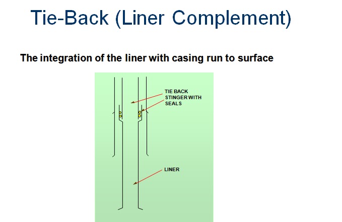
-Tie-back/liner complement:
From top of existing liner to surface, or further up casing to cover corroded or damaged zone.
Tie-Back (Liner Complement)
Procedure for Setting Liner
-RIH with drillpipe
-At liner hanger depth, condition mud
(Reciprocation / Rotation)
-Release slips (liner hanger)
(Rotation - mechanical pressure - hydraulic)
-Set slips, release liner weight, check to see if running tool is free
-Pump mud - to ensure free circulation
-Cement / Displace / Bump plug / Bleed off
-Release setting tool
-POOH above TOC and circulate
NOTE: A liner swivel can be run below the hanger to ensure that the tool can be rotated even if the liner is stuck or set.

  Job Procedure Liner


-Pressure test lines.
-Pump wash/spacer.
-Pump slurry.
-Drop "Pump Down" plug (or drill pipe wiper dart).
-Displace 
To running tool 
Shear "Wiper Plug”
Displace to Float Collar
-Bump plug/check for returns.
-Release tool.
-Pull up to T.O.C. and circulate.
Liner Overlap 
-Cementing the liner “lap” is critical .
-Too much cement above the liner hanger is not recommended
-So make sure that “uncontaminated” cement is present at the liner lap - washes and spacers / WELLCLEAN II
-If not, there is communication from the annulus to the formation
 
 Recommendations for Liner Cementing
 
 
-Ensure rheology of cement system is adequate for 100% mud removal
-Turbulent flow, if possible
-Consider 5 - 10 min. “contact time” at liner lap
-Batch mix cement
-Minimize U-tubing effect
-Rotation of liner during cementing (special bearing in tool)
-Adequate mud conditioning prior to cementing
Example Calculation - Liner
-Well Information: 
9-5/8" 47 lb/ft intermediate casing from surface to 6500 feet
7" 29 lb/ft intermediate liner from 6200 ft to 10,500 feet
6" open hole to TD at 14,500 feet
Drill pipe 3-1/2" 13.30 lb/ft 
4-1/2" 16.60 lb/ft liner required from 14,400 ft to 400 ft inside 7" liner.
Float collar 80 feet above shoe.
-Cement required to top of liner with 20% excess in open hole
*Calculate:
Slurry Volume and Displacement 
 
  Liner Example Calculations - Results


 Conclusion


-Liners have many applications
-The main feature is that normally you have small volumes of slurry and high pressures during the job.
-Liner overlap is the most critical part to cement correctly
-Even though most of the times we are not at charge of the hardware (liner hanger, cement head, etc.), we must have knowledge of what has been run in the hole, and the way it works.
-It is important to slow down the displacement to avoid excessive pressures (shear pins, end of displacement)
 
 
Case history
Critical water zones in a North African field required isolation with an intermediate casing 
 
cemented in two stages. This operation increased rig time, cost and potential trouble for this
 
casing operation. Because the stage tool created a potential future weakness in the 
 
intermediate casing string, the production casing had to be run to surface to cover the stage
 
tool and protect it from future production operations.
 
The casing program was redesigned using LiteCRETE technology to replace the two-stage 
 
intermediate casing with a single-stage casing requiring only one cement slurry. This saved 
 
stage-tool-running time, associated rig costs and eliminated the risk associated with a stage 
 
tool. Instead of a full production string, a production liner was then run back into the 
 
intermediate casing, saving additional time and expense in well construction.
 
LiteCRETE technology offers a well-construction solution with low permeability and low 
 
density. Superior-quality cement columns can be pumped higher in the annulus so 
 
multiple-stage cementing becomes unnecessary.