Showing posts with label Directional drilling. Show all posts

METHODS OF DEFLECTING A WELLBORE con't 3

Downhole Motor

  • Turbodrills have been around for many years but are seldom used for directional drilling 
  • Turbodrills have very high rotary speeds (500 to 1200 rpm)  
  • Because of the high rpm, bit life is limited
  • Diamond and PDC bits are more applicable to turbodrills
  • Turbodrills have low starting torque
  • If the motor is in a bind, it is hard to get the motor started
  • Turbodrills are used in directional drilling where the temperature exceeds the limit of a positive displacement motor
Positive displacement motors were introduced in the 1960’s


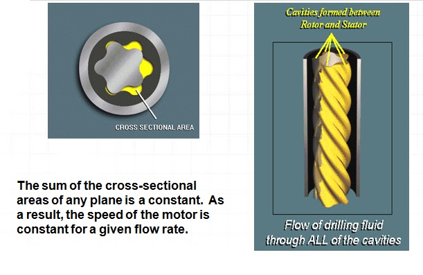
Rotor/stator configuration


Speed (RPM) / Torque (Ft-Lbs.)


  • For best performance, the power section should be matched to the bit and formation being drilled.  The speed and torque of a power section is directly linked to the number of lobes on the rotor and stator.  The higher the number of lobes, the higher the torque and the lower the RPM.
 

Dump sub
  •         Not often used
  •   Allows string to fill or drain when tripping
  •   Allows low volume circulation in stuck bit situations
 
Power pack section
Rotor is hard
Stator is flexible
Stator housing is thin
PDM is not a drill collar
 
 
  •  Reverse application of the Moineau pump principle
  •  Elastomer lined - steel tube stator
  •  Chrome  coated steel rotor
  •  Converts Hydraulic HP (flow & pressure) to Mechanical HP (rpm & torque) There are three main producers of motor  power sections in the world:
 
Typical PDM power curve
 
  •  Rotor is coupled to transmission
  •  Transmission shaft is coupled to the bearing pack
  •  The adjustable bent housing enables the bend to be changed at the wellsite
  •  The housing can be adjusted 0.26 to 3.0 degrees depending upon motor size
  
Bearing function
  •   On bottom thrust bearings carry force from the bit    (WOB)
  •   Off bottom thrust bearings carry the hydraulic load  of the mud and weight of the rotor
  •   Radial bearings carry side loads
  •   Flow restrictor diverts a portion of the mud for    lubrication

METHODS OF DEFLECTING A WELLBORE con't 2

Rotary BHA
  • The rotary BHA consists of a bit, drill collars, stabilizers, reamers, subs and other special tools run below the drill pipe
  • Motors were used to put the wellbore on course and rotary BHA’s were used to drill the majority of the well
  • Even though rotary assemblies are used only occasionally, we will still look at them
  • Steerable motor assemblies in the rotating mode are still rotary BHA’s subject to the same influences as the rotary BHA
  • A slick assembly is simply a bit and drill collars
 
  • The deviation tendency is caused by the bending of the drill collars
  • The point at which the collars touch the wall of the hole is the tangency point
  • The resultant force applied to the formation is not in the direction of the hole axis but in the direction of the drill collar axis
  • The resultant force can be broken up into its components FB and FP
 
  • FB is the side force caused by the bending of the collars or building force
  • FP is the force due to gravity or pendulum force
  • Ideally, if
  1.        FP > FB, the hole inclination will drop
  2.        FP < FB, the hole inclination will increase
  3.       FP = FB, the hole inclination will remain constant
  • The building force can be increased by increasing bit weight, which drives the tangency point down
  • The building force is also affected by the stiffness of the collars
  • Stiffer collars will bend less
  • As the diameter of the collar increases, the stiffness of the collar increases

  • The pendulum force can be increased by reducing bit weight and using larger diameter collars
  • ØSome inclination is required to have a pendulum force
  • ØFor a slick assembly, the building and pendulum force will balance at relatively low inclinations; therefore, they are not expected to build much inclination


  • So why does the inclination exceed 1 to 2o in some areas while it does not in other areas?
  • If the bed dip is relatively flat, we seldom have any deviation problems
  • When bed dip is encountered, we can experience deviation problems in harder rock
  • Deviation problems are associated with formation dip
  • The anisotropy of the formation causes deviation


  • If the formation deviation tendency can be defined as a force FF, the resultant force at the bit would be
    -FB + FP + FF   
  •  The wellbore will continue to build angle until the sum of the forces is equal to zero 
  •  Unfortunately it is difficult to define FF and it changes with depth     
Rule of thumb
  • If the bed dip is less than 45 degrees, the bit will have a tendency to deviate perpendicular to the bed dip (up dip)   
  • If bed dip is above 65 degrees, the bit will have a tendency to deviate along the bed dip 
  • Between 45 and 65 degrees, the bit can do either
  • In directional drilling, it is the difference between the bit angle and the formation dip 
  • The formation may want the bit to drop inclination when the wellbore is at an inclination greater than bed dip 
  • The two forces associated with a rotary assembly are the building force (FB) and the dropping force (FP) 
  • If we want to make a building assembly, the building force must be maximized 
    Stabilizers are used as fulcrums in order to increase the side force at the bit


Building assembly
A building assembly is constructed by placing a stabilizer near the bit
Bending of the drill collars above the stabilizer causes the building force at the bit to increase substantially
  • At low inclinations, the drill collars are bent by increasing bit weight
  • At higher inclinations, gravity will bend the collars and the build tendency is less affected by bit weight   
  • In order to make a dropping assembly, the pendulum force is maximized by placing a stabilizer at least 30 to 90 feet above the bit
 

  •     If the collars touch the wall of the hole between the stabilizer and the bit, the tangency point becomes the place where the collars first touch the wall of the hole
  •     If the stabilizer is too far above the bit, the collars will touch the wall and the pendulum force will be reduced  
-A holding assembly is constructed by placing stabilizers closer together so that the collars are more rigid
-Bit side force is minimized
  • Holding inclination is the most difficult with a rotary assembly
  • Analysis by Amoco indicated that
  1. -Assembly A proved to be the most successful even though it maintained inclination only 60 percent of the time
  2. -Assembly B maintained inclination less than 50 percent of the time
  3. -Assembly C held inclination less than 50% of the time 
To better understand the forces on a rotary BHA, lets look at a single stabilizer assembly with the stabilizer positioned at various distances from the bit


  • Rotary BHA’s were not very efficient as it was difficult to predict the actual performance of any rotary BHA
  • Frequent trips were required to change stabilizer placement and size
  • The build, hold or drop tendency of the rotary BHA could be adjusted but the walk tendency could not be changed substantially
  • A pure rotary assembly is used only occasionally today
  • Derivatives of the rotary assembly are used frequently
  • Steerable motor assembly 
  • Rotary steerable assembly
oil spill gulf gulf gulf oil mexico oil spill mexico gulf of mexico oil spill bp bp bp oil oil spill 2010 bp gulf gulf of mexico gulf oil mexico obama oil spill oil spill 2010 oil spill bp  oil spill florida oil spill gulf
US sues BP, 8 other companies in Gulf oil spill Gulf oil spill recovery exec dead in plane crash Ex-CEO says BP was unprepared for oil spill BP's oil spill costs grow Scientists to see if oil spill hurt deep sea life Depression soars among Gulf residents after oil s


pill BP spent $93M on advertising after Gulf oil spill


METHODS OF DEFLECTING A WELLBORE

METHODS OF DEFLECTING A WELLBORE con't


METHODS OF DEFLECTING A WELLBORE con't 4


METHODS OF DEFLECTING A WELLBORE con't

Jetting
Jetting was used as an alternative to whipstocks 
  • Jetting was only effective in softer rocks since formations have to be eroded to change the trajectory of the wellbore 
  • A bit with a larger diameter nozzle facing the side of the hole was used to erode the formation to one side of the bit                       


  • The larger nozzle was oriented in the desired direction
  • The formation was washed as the assembly was lowered into the hole 

  •  If the rocks were too soft, the entire bottom of the hole may wash out without substantially altering the hole trajectory
  • In harder formations, the bit often had to be turned slightly left and right to erode the side of the hole 
  • Penetration rate while jetting, was very slow 
  • Once a portion of the hole had been jetted and the bit worked to bottom, the assembly was rotated to continue drilling ahead   
  • Jetting created a high dogleg severity in a short interval even though surveys may not indicate it   
  • The jet deflection bit was actually the first steerable assembly 
  1.   While jetting, the drill string was not rotated in order to effect a trajectory change (slide drilling) 
  2.   After jetting, the drill string was rotated to drill ahead

METHODS OF DEFLECTING A WELLBORE


Any number of directional tools can be used to deflect a wellbore or make the wellbore go where we want it to go
Methods of Deflection
  • Whipstocks
  • Jetting
  • Rotary BHA
  •  Rotary BHA with adjustable stabilizer
  • Motor
  •       Steerable motor
  • Rotary steerable assembly
  • Over time, the tools we have used to deviate a wellbore in the desired direction have changed

  • Newer and more efficient tools have been developed and will be developed in the future
Significant advances in directional drilling technology
 Whipstock
  •      One of the earliest tools used in the industry was the whipstock
  •  The whipstock is a metal wedge placed in the wellbore that causes the bit to deviate
  •     In the early years of the petroleum industry, they were used to sidetrack wells if a portion of the drill string became stuck
  •      As directional drilling started in the 1930’s, whipstocks were oriented and used to change the inclination and azimuth of the wellbore Whipstocks were not very efficient
  •      In order to use a whipstock, the drill string was pulled from the hole and a whipstock was run into the well
  •      On a retrievable whipstock, a pin was sheared and the bit drilled off the whipstock
  •  
  Retrievable whipstock

  •      Because the bit had to be run in with the whipstock, it was a smaller diameter than the hole
  •      A second trip was made to open the hole to full gage 
  •   In harder rock, a reaming trip may have been required
  •   Using the whipstock required a minimum of three trips, which was not cost effective
  •   Permanent whipstocks were no better even though a full sized bit could be used to drill off it
  •      Today, whipstocks are used frequently to sidetrack out of casing
  •      The majority of casing sidetracks are now performed with a whipstock 


METHODS OF DEFLECTING A WELLBORE con't