Showing posts with label prodaction. Show all posts

Gas Lift Optimization cont 1

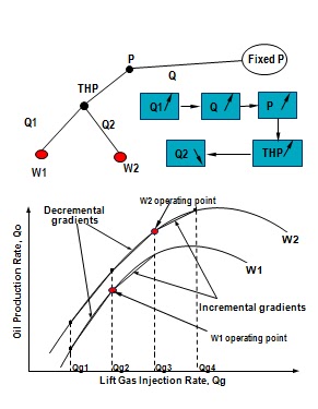
Wells that can only Flow under gas Lift


WTEST can be used to revive a dead well by adding lift gas
The WIG  is calculated based on the total number of lift gas increments that would give the well the largest ratio of oil production rate to lift gas injection rate (line 
O-A)
If a well is only just able to flow (at point B), the WDG is calculated based on all the increments (line O-B)
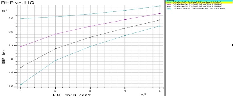
Using the GLO Facility (1)


Prepare the VFP Tables - VFPPROD
ALQ = lift gas injection rate (GRAT)
VFPTABL
1 = Linear interpolation
2 = Cubic Spline interpolation
LIFTOPT keyword
Activates the GLO facility
Sets: 
incremental size for lift gas injection rate
Min economic gradient
Min interval between GLOs
GLO during each of the 1st NUPCOL iterations?
 WLIFTOPT keyword 
Well name 
Is the well to be optimized using GLO? 
Max lift gas injection rate 
Weighting factor for preferential allocation of lift gas 
Min lift gas rate 
>0 = Min rate unless the well cannot flow 
<0 = at least enough lift gas to enable the well to flow 
allocate in decreasing order of weighting factor to group of wells 
Note: By default, no lift gas is allocated if the group’s target can be met unless the weighting factor > 1.0
GLIFTOPT keyword (optional)
group lift gas supply limits
group lift gas rate = SUM well lift gas rate x efficiency factor
maximum total (produced + lift ) gas rate for the group
Group Production Rate Limits
Lift gas is allocated if a group/field cannot reach its OPR
subject to lift gas supply limits, other phase limits (unless 
necessary to make the well’s Min lift requirement & the well’s
 weighting factor > 1.0)
Rates could change if GLO is only in the 1st iteration
Use with network option
GLO when the network is being balanced 
if the network is only balanced in the 1st iteration, GLO is only in the start of the time step
if the network is only balanced in the 1st NUPCOL iterations, GLO will also be carried out in the 1st NUPCOL iterations
Computing time increases with (No. wells)2
effect of lift gas in pipe line:
item 6 of GRUPNET
‘FLO’ = add wells’ lift gas to the branch. The total GFR is used in VFP table
‘ALQ’ = total ALQ = SUM of wells’ ALQs = the total ALQ is used in VFP table
  
Output
Gas lift injection rate: FGLIR, GGLIR, WGLIR
well oil gas lift ratio: WOGLR 
FGPR & WGPR do not include injected lift gas
Restrictions
Do not use
GLIFTLIM - Max(sum ALQ), Max No. wells on artificial lift
the lift switching option in WLIFT
Use GLIFTOPT and WLIFTOPT instead
Flux Boundary Conditions facility should no be used
lift gas supplied to wells outside the flux boundary is not taken into account


Gas Lift Optimization


A gas-lift system provides production energy by injecting gas into the production fluid column, thereby reducing the hydrostatic pressure and enabling improved reservoir production.
 
Purposes of Gas Lift optimization

optimizing gas lift to individual wells
What is the optimum amount of lift gas required for a well to achieve its production target?


optimizing gas lift within a group of wells
How should a limited supply of lift gas be best distributed among the individual wells in order to achieve its group production target?


optimizing gas lift within a simple network
For sub-sea manifold group of wells, how do the pressure losses in a flow line affect the optimum distribution of lift gas to the wells?
 
Gas Lift without optimization 

 
VFPPROD -record 1, item 7 - definition of ALQ: GRAT, IGLR, TGLR
WCONPROD - item 12
WELTARG - item 2 -LIFT
WLIFT - item 5 - new ALQ; item 10 incremental of ALQ
 
Optimizing Individual Wells

Divide the lift gas supply into discrete increments of uniform size
Examine effect of increasing lift gas to each well by one increment. Calculate the well’s weighted incremental gradient (WIG)
Examine effect of reducing lift gas to each well by one increment. Calculate the well’s weighted decremental gradient (WDG)
Add lift gas to the well as long as its weighted incremental gradient > the minimum economic gradient (MEG)
 Optimizing Groups
 
Update the distribution of the lift gas increments currently allocated to the group:
move an increment from well w2 to w1 if maxWIG(w1)>minWDG(w2)
until there is no exchange
Remove from the group any surplus increments
>production rate limit
>lift gas supply limit
well’s WDG<MEG
Add lift gas increment to the well
with largest WIG>MEG
<its own lift gas supply limit 
<its group’s lift gas supply limit
 
 Optimizing Gas Lift in a Network
 
Whenever a lift gas increment is added or subtracted,  WIG & WDG must be 
recalculated for all the wells in the field
reason: change in Q affects THPs of other wells in the network
Each time WIG & WDG are recalculated, the whole network must be rebalanced
computation time proportional to square of the no. of wells multiplied by no. of lift gas increments added/subtracted
recommend to use NETBALAN to decrease the network convergence tolerance 
by a factor of 10. 


workover (Why do we make work over?)


Workovers Performed To

Increase or restore hydrocarbon production 
Decrease water production
Repair mechanical failures
Common Reasons for a Workover 
Some of the more common reasons for a workover are:
Repair mechanical damage
Stimulate an existing completion
Complete into a new reservoir
Complete multiple reservoirs 
Reduce/eliminate water/gas production
Reduce/eliminate water coning
Repair faulty cement jobs
 
Repair Mechanical Damage
Reasons for Workover Work

Mechanical damage can take on many forms from failed tubing or downhole tools such as packers, sliding sleeves, gas lift equipment, tubing or wireline retrievable safety valves, to failed or failing wellheads. In some cases the repair can be performed without killing the well, in other cases the well has to be killed to perform the work safely.


  Reservoir Simulation

Reservoir stimulation is usually accomplished by introducing a mild acid through the perfs and into an existing producing reservoir for the purpose of dissolving acid soluble solids and regaining or restoring production. This can be done by a coiled tubing unit, snubbing unit, or small tubing unit.
  
Completing a New 
Reservoir
Completing to a new reservoir is often done when a well is drilled through multiple productive layers and the lower zone is finally depleted. The new completion might be as simple as shifting a sleeve open to allow flow, or may require that the lower zone be plugged and abandoned before the upper zone is allowed access into the wellbore.
  

Completing an Existing Zone
In this case the lower depleted zone is isolated with a cement plug prior to opening the sleeve adjacent to the next zone to be produced.
After the cement plug is in place and tested, the sleeve can be opened and the next zone produced
  

Recompleting an Existing Zone
Production tubing above the depleted zone has been cut and removed and the lower zone isolated with a cement plug. The new completion is run in the hole adjacent to the reservoir to be produced, the zone is perforated. And production begins.

Here the lower depleted zone has been isolated with a plug conveyed by either coiled tubing or wireline. After the plug has been successfully set and tested the sliding sleeve is opened allowing production from the upper zone.


  Completing Multiple Reservoirs
A dual completion, such as this one, allows for production from two zones simultaneously.


Unwanted Water Reduction
Water, the lowermost fluid in a reservoir, appears as the lighter fluids are depleted. Initial production may contain a degree of water, but the oil-to-water ratio usually decreases throughout the life of the well. Remediation for this problem can be squeezing affected perforations – but this solution is only temporary.
 

Water Coning
Excessive production rates can initiate water coning. Water, which may be the the drive mechanism or the lower fluid strata in the reservoir, is pulled up into the perfs. Water coning can be controlled to some extent by reducing the production rate. But, usually, the affected perforations are squeezed resulting in lower production outputs on a daily basis.
  

Repair Failed Cement Jobs
Evidence of a failing cement job are usually manifested as pressure appearing on the intermediate casing string and the presence of chunks of cement in the choke body. This may also be accompanied by a decrease in daily production as surface lines can become clogged with cement. Repairing this usually entails killing the well, squeezing cement into the perforations, recompleting and reperforating the well.
  

Unwanted Gas Production
In a gas cap driven reservoir, the gas cap expands as oil is drawn from the reservoir. Eventually the expanding gas cap can encroach on the perforations and gas production will begin. The drawbacks are: the drive mechanism is being produced and the production train may not be able to handle the gas being produced. This is temporarily remedied by squeezing the perfs. But eventually mostly gas will be produced as the producible oil is depleted.