Tubulars lec ( 5 )

Introduction

The design of an efficient, safe and economical completion system is dependent
upon the acquisition of accurate data and the selection of appropriate
components. Since the ultimate success of the completion system is dependent
on its successful installation, the installation procedures should also be given
some consideration.
Completion designs will vary significantly with the variation of the following
reservoir and location characteristics:
  •  Gross production rate
  •  Well pressure and depth
  •  Formation properties
  •  Fluid properties
  •  Well location
  •  Existing stock

Completion Equipment
Selection

As with all downhole components, data on completion components must include
full details of dimensions, profiles and connections. This is a basic requirement
of all downhole equipment, but is of special significance in completion design
and installation since many future well service activities will require throughtubing
access.

Basic Dimensional Data


  •  Length (depth)
  •  ID/OD (internal & external diameters)
  •  Thread type

Tubular Components

When completing a well, the proper selection of tubular components is possibly
one of the most important decisions. Tubular components come in a number of
different grades and diameters and several factors must be considered prior to
selection.
The higher formation pressures encountered in recent years requires tubing
and components have a greater yield strength. In addition, improved sealing
mechanisms at connections are also required. The types of connections
available have also increased. Those involved with completion design and
installation must understand the proper application of common tubing and
component types. Similarly, a good working knowledge of common seals and
connections is necessary.


Inspection Procedures


A critical part of any well completion operation is the inspection of components
prior to final assembly and installation. Completion specialists and supervisors
must be aware of necessary inspection procedures, as well as the basic handling
procedures for each completion component.

Tubing String
Specification

Tubing generally provides the primary conduit from the producing interval to
the wellhead production facilities. Therefore, the proper selection, design and
installation of tubing is a very important part of any completion system.


Tubing Length 

Tubing joints vary in length from 18 to 35 feet although the average tubing
joint is approximately 30 feet. In any tubing shipment the joint length will vary,
so accurate measurement of each joint is essential. Pup joints (for spacing out
the string) are available in shorter lengths (2’ - 20’) in 2’ increments.

Tubing Diameter

Tubing is available in a range of OD sizes. The most common sizes are 23/8", 27/8",
31/2" and 41/2" (51/2", 7" and 95/8" tubing is fairly common in some areas e.g., the
North Sea). The API defines tubing as pipe from 1" to 41/2" OD. Larger
diameter tubulars being termed casing (41/2" to 20").

Tubing Construction 

Most types of tubing joint are threaded on each end (pin end) and connected
by couplings (box). The pipe used for production tubing may be manufactured
by one of two methods

Tubing Classification
Criteria

The following criteria are used to classify or specify tubing string material and
joint construction:


API Tubing Grades 

Much of the tubing used is manufactured according to API specifications and
must undergo a wide variety of tests and checks before shipment and
installation.
Standard API steel grades for tubing are J-55, C-75, L-80, C-95, N-80, P-105 and
V-150. Grades C-75, L-80 and C-95 are intended for hydrogen sulfide service
where higher strength than J-55 is required.
NOTE: L-80 may be 4130/4140 LHT material, 9Cr LHT, or 13Cr material.


Color Bands


The grade of new tubing can be identified by color bands:


High Strength
Tubing

High strength tubing is generally considered to include grades with a yield
strength above 80,000 psi. C-75, L-80 and N-80 are often included because
their as-manufactured yield strength often exceeds 80,000 psi. High strength
tubing, particularly P-105, presents an increased sensitivity to sharp notches
or cracks.
Any sharp-edged notch or crack in the surface of a material is a point of stress
concentration which tends to extend the crack progressively deeper into the
material, much like driving a wedge. Low strength materials are soft and ductile
and will yield plastically to relieve the stress concentration. High strength
materials do not yield to relieve the stress concentration and tend to fatigue or
fail more rapidly when subjected to cyclic stresses.

Maximum Allowable
Stress

Calculation of the maximum allowable stress of a certain pipe is carried out by
multiplying the minimum cross sectional area of the pipe, times the minimum
yield strength rating of the pipe


Well Completion Planning con't lec ( 4 )

Drilling

Drilling and associated operations, (e.g., cementing), performed in the pay
zone must be completed with extra vigilance. It is becoming increasingly
accepted that the prevention of formation damage is easier and much more
cost effective, than the cure. Fluids used to drill, cement or service the pay
zone should be closely scrutinized and selected to minimize the likelihood of
formation damage.

Evaluation

Similarly, the acquisition of accurate data relating to the pay zone is important.
The basis of several major decisions concerning the technical feasibility and
economic viability of possible completion systems will rest on the data obtained
at this time.

Pre-Completion

 A precompletion stimulation treatment is frequently conducted. This is often
part of the evaluation process in a test-treat-test program in which the response
of the reservoir formation to a stimulation treatment can be assessed..
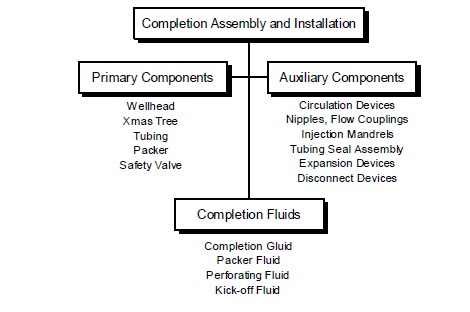
Completion Assembly
and Installation


With all design data gathered and verified, the completion component selection,
assembly and installation process commences. This phase carries importance
since the overall efficiency of the completion system depends on proper
selection and installation of components.
A “visionary” approach is necessary since the influence of all factors must be
considered at this stage, i.e., factors resulting from previous operations or
events, plus an allowance, or contingency, for factors which are likely or liable
to affect the completion system performance in the future.
The correct assembly and installation of components in the wellbore is as
critical as the selection process by which they are chosen. This is typically a
time at which many people and resources are brought together. The demands
brought by high and mounting, daily charges imposes a sense of urgency
which requires the operation to be completed without delay. To ensure the
operation proceeds as planned, it is essential that detailed procedures are
prepared for each stage of the completion assembly and installation. The
complexity and detail of the procedure is largely dependent on the complexity
of the completion.

Primary Completion
Components
Primary completion components

 are considered essential for the completion to
function safely as designed. Such components include the safety valves, gas
lift equipment, tubing flow control tools and packers. In special applications,
(e.g., artificial lift), the components necessary to enable the completion system
to function as designed will normally be considered primary components.

Completion System 

Several types of devices, with varying degrees of importance, can be installed
to permit greater flexibility of the completion. While this is generally viewed as
beneficial, a complex completion will often be more vulnerable to problems or
failure, (e.g., due to leakage).
The desire for flexibility in a completion system stems from the changing
conditions over the lifetime of a well, field or reservoir. For example, as the
reservoir pressure depletes, gas injection via a side pocket mandrel may be
necessary to maintain optimized production levels. The selection of completion
components and fluids should reflect a balance between flexibility and simplicity.

Completion Assembly
and Installation Factors

Completion Fluids

A significant fluid sales and service industry has evolved around the provision
of completion fluids. Completion fluids often require special mixing and hauling
procedures, since (a) the level of quality control exercised on density and
cleanliness is high and (b) completion fluids are often formulated with
dangerous brines and inhibitors.

Initiating Flow

The process of initiating flow and establishing communication between the
reservoir and the wellbore is closely associated with perforating operations. If
the well is to be perforated overbalanced, (higher pressure in the wellbore than
in the formation) then the flow initiation and clean up program may be dealt
with in separate procedures. However, if the well is perforated in an
underbalanced condition, (lower pressure in the wellbore than in the formation)
the flow initiation and clean up procedures must commence immediately upon
perforation.Production Initiation


Underbalanced
Perforating

Perforating when the reservoir pressure is substantially higher than the wellbore
pressure is referred to as under-balanced perforating. While the reservoir/
wellbore pressure differential may be sufficient to provide an underbalance at
time of perforation, the reservoir pressure may be insufficient to cause the well
to flow after the pressure has equalized.
Adequate reservoir pressure must exist to displace the fluids from within the
production tubing if the well is to flow unaided. In the event the reservoir
pressure is insufficient to achieve this, measures must be taken to lighten the
fluid column typically by gas lifting or circulating a less dense fluid.
The flow rates and pressures used to exercise control during the clean up
period are intended to maximize the return of drilling or completion fluids and
debris. This controlled backflush of perforating debris or filtrate also enables
surface production facilities to reach stable conditions gradually.

Wellbore Clean Up

Wellbore cleanup is normally not required with new completions. However, in
wells which are to be re-perforated or in which a new pay zone is to be opened,
a well bore clean up treatment may be appropriate. There is a range of perforation
treatments associated with new or recompletion operations.

Overbalanced
Perforating

Perforating when the wellbore pressure is higher than the reservoir pressure is
referred to as Overbalanced Perforating. This is normally used as a method of
well control during perforating. The problem with this method is it introduces
wellbore fluid into the formation causing formation damage.
It is sometimes desirable to place acid across the interval to be perforated when
overbalanced perforating. The resulting inflow of acid results is a matrix type
acid treatment occurring.

Extreme Overbalance
Perforating

In this type of perforating operation the wellbore is pressured up to very high
pressures with gas (usually nitrogen). When the perforating guns are detonated
the inflow of high pressure gas into the formation results in a mini-frac, opening
up the formation to increase inflow.


Stimulation Treatments


Acid Washing
of Perforations


Perforation acid washing is an attempt to ensure that as many perforations as
possible are contributing to the flow from the reservoir. Rock compaction, mud
and cement filtrate and perforation debris have been identified as types of
damage which will limit the flow capacity of a perforation and therefore,
completion efficiency.
If the objective of the treatment is to remove damage in or around the
perforation, simply soaking acid across the interval is unlikely to be adequate.
The treatment fluid must penetrate and flow through the perforation to be
effective. In which case all the precautions associated with a matrix treatment
must be exercised to avoid causing further damage by inappropriate fluid
selection.

Hydraulic Fracturing


Hydraulic fracturing treatments provide a high conductivity channel through
any damaged area and extending into the reservoir. The natural fractures
within the formation material are opened up using hydraulic fluid pressure.
Commonly a proppont such as sand is introduced to ‘prop’ the fracture open
after the pressure is removed, but still will allow flow of reservoir fluids and
gases. Hydraulic fracturing treatments require a detailed design process which
is usually performed by the service supplier.

Well Service
and Maintenance
Requirements

The term “well servicing” is used (and misused) to describe a wide range of
activities including:
  •  Routine monitoring
  •  Wellhead and flowline servicing
  •  Minor workovers (through-tubing)
  •  Major workovers (tubing pulled)
  •  Emergency containment or response
Well service and maintenance preferences and requirements must be considered
during the completion design process. With more complex completion systems,
the availability and response of service and support systems must also be
considered.
Well bore geometry and completion dimensions determine the limitations of
conventional slick line, wireline, coiled tubing or snubbing services in any
application.

Logistic and
Location Constraints

Restraint imposed by logistic or location driven criteria often compromise the
basic cost effective requirement of a completion system. Special safety and
contingency precautions or facilities are associated with certain locations,
(e.g., offshore and subsea).

Logistic and
Location Criteria


Client Requirements


The completion configuration and design must ultimately meet all requirements
of the client. In many cases, these requirements may not be directly related to
the reservoir, well or location (technical factors). An awareness of these factors
and their interaction with other completion design factors can help save time
and effort in an expensive design process.
The following factors are common criteria which must be considered:
  •  Existing stock or contractual obligation
  •  Compatibility with existing downhole or wellhead components
  •  Client familiarity and acceptance
  •  Reliability and consequences of failure

Regulatory Requirements

There are several regulatory and safety requirements applicable to well
completion operations. These must satisfied during both the design and
execution phases of the completion process.
  •  Provision for well-pressure and fluid barriers
  •  Safety and operational standards
  •  Specifications, guidelines and recommendations
  •  Disposal requirements
  •  Emergency and contingency provision

Revenue and Costs

When completing an economic viability study, or comparison, the costs
associated with each of the following categories must be investigated.
  •  Production revenue
  •  Capital cost (including completion component and installation cost)
  •  Operating cost (including utilities and routine maintenance or
servicing cost, also workover, replacement or removal cost)
Installation costs are significant if special completion requirements impact the
overall drilling or completion time. The actual cost of completion components
is often relatively insignificant when viewed alongside the value of incremental
production from improved potential or increased uptime.


Economic Factors


A rudimentary understanding of the economic factors is beneficial.

  •  Market forces (including seasonal fluctuations and swing
production)
  •  Taxation (including tax liability or tax breaks)
  •  Investment availability


Company Objectives


A measure of success can only be made if there exists clearly stated objectives.
Such objectives may macroscopic, but nonetheless will influence the specific
objectives as applied to an individual well or completion. In addition, the wider
company objectives may allow clarification of other factors, (e.g., where two or
more options offer similar or equal benefit and no clear selection can be made
on a technical basis).

  •  Desired payback period
  •  Cash flow
  •  Recoverable reserves

Well Completion Planning lec ( 3 )

Introduction

Planning a completion, from concept through to installation, is a complex
process comprising many phases. Many factors must be considered, although
in most cases, a high proportion can be quickly resolved or disregarded.
Regardless of the completion design complexity, the basic requirements of any
completion must be kept in mind throughout the process. A completion system
must provide a means of oil or gas production (or injection) which is safe,
efficient, reliable and economical.
Ultimately, it is the predicted technical efficiency of a completion system, viewed
alongside the company objectives that will determine the configuration and
components to be used.

Completion
Planning Process


This section outlines the principal factors to be considered when planning an
oil or gas well completion. In addition to the technical influences on completion
design and selection, economic and non-technical issues are also detailed.
The relevance of these issues, in common with technical details, is dependent
upon the circumstances pertaining to the specific well, completion or field
being studied.
Although many wells (and fields) may be similar, the success of each completion
system is based on the individual requirements of each well. Therefore, it is
necessary to review and amend generic design or installation procedures as
required.

Principal Phases of
Well Completion Design


Impact of
Non-Optimized
Completions

The economic impact of designing and installing non-optimized completions
can be significant. Consequently, the importance of completing a thorough
design and engineering process must be stressed. Delaying the commencement
of the wells pay out period is one example of how non-optimized completion
design, or performance, can affect the achievement of objectives. However,
while reducing installation cost and expediting start-up are important objectives,
far-reaching objectives such as long-term profitability must not be ignored. As
illustrated, a more costly and complex completion may provide a greater return
over a longer period. In addition, the consequences of inappropriate design
can have a significant effect, (e.g., requiring premature installation of velocity
string or artificial lift).

Optimized Completion
System


Reservoir Parameters

The type of data outlined in this category are obtained by formation and
reservoir evaluation programs such as coring, testing and logging. Typically,
such data is integrated by reservoir engineers to compose a reservoir model.
The reservoir structure, continuity and production drive mechanism are
fundamental to the production process of any well. Frequently, assumptions
are made of these factors which later prove to be significant constraints on the
performance of the completion system selected.
Physical characteristics of the reservoir are generally more easily measured or
assessed. Pressure and temperature are the two parameters most frequently
used in describing reservoir and downhole conditions. The effects of
temperature and pressure on many other factors can be significant. For example,
corrosion rates, selection of elastomer or seal materials and the properties of
produced fluids are all affected by changing temperature and pressure.

Components of a
Reservoir Model


Produced Fluid
Characteristics

The ability of the reservoir fluid to flow through the completion tubulars and
equipment, including the wellhead and surface production facilities, must be
assessed. For example, as the temperature and pressure of the fluid changes,
the viscosity may rise or wax may be deposited. Both conditions may cause
unacceptable back-pressure, thereby dramatically reducing the efficiency of
the completion system.
Although the downhole conditions contributing to these factors may occur
over the lifetime of the well, they must be considered at the time the completion
components are being selected. Cost effective completion designs generally
utilize the minimum acceptable components of an appropriate material. In
many cases, reservoir and downhole conditions will change during the period
of production. The resulting possibility of rendering the completion design or
material unsuitable should be considered during the selection process.

Components of Produced
Fluid Characteristics

Wellbore Construction

The drilling program must be designed and completed with the scope and
limits determined by the completion design criteria.
Most obvious are the dimensional requirements determined by the selected
completion tubulars and components. For example, if a multiple string
completion is to be selected, an adequate size of production casing (and
consequently hole size) must be installed. Similarly, the wellbore deviation or
profile can have a significant impact.

Components of
Wellbore Construction


Introduction To Completions lec ( 2 )

Naturally Flowing Completions

Wells completed in reservoirs which are capable of producing without assistance
are typically more economic to produce. However, in high-temperature, highpressure
applications, a great deal of highly specialized engineering and design
work will be required to ensure that safety requirements are met.
In general, naturally flowing wells require less complex downhole components
and equipment. In addition, the long-term reliability and longevity of the
downhole components is generally better than that of pumped completions.
In many cases, wells may be flowed naturally during the initial phases of their
life, with some assistance provided by artificial lift methods as the reservoir is
depleted. Such considerations must be reviewed at the time of initial completion
to avoid unnecessary expense and interruption of production.

Artificial Lift Completions

All pumped, or artificially lifted, completions require the placement of
specialized downhole components. Such components are electrically or
mechanically operated, or are precision engineered devices. These features
often mean the longevity or reliable working life of an artificial lift completion
is limited. In addition, the maintenance or periodic workover requirements
will generally be greater than that of a naturally flowing completion.

Artificial Lift Methods

Pumped or assisted lift production methods currently in use include the
following:
  •  Gas lift
  •  Electric submersible pump
  •  Plunger lift
  •  Hydraulic or Jet Pump
  •  Variable Cavity Pump (VCP)
  •  Hydraulic or Jet pump
  •  Progressive cavity pump (PCP)


Single Zone Completion

 In single zone completions, it is relatively straight forward to produce and
control the interval of interest with the minimum of specialized wellbore or
surface equipment. Since typically one conduit or tubing string in involved,
the safety, installation and production requirements can be easily satisfied.
In most single zone completions, a packer (or isolation device) and tubing
string is used. This provides protection for the casing or liner strings and
allows the use of flow control devices to control production.
The complexity of the completion is determined by functional requirements
and economic viability. Several contingency features may be installed at a
relatively minor cost at the time of the initial installation. Consequently,
consideration must be given to such options during the initial design phase.

Multiple Zone Completions

Multiple zone completions are designed to produce more than one zone of
interest. However, there are many possible configurations of multiple zone
completion, some of which allow for selective, rather than simultaneous
production.


Phases of Well Completion

A sequential and logical approach to the design and execution process is
required. Since the ultimate efficiency of a completion is determined by
operations and procedures executed during almost every phase of a wells life,
a continual review and monitoring process is required. Typically this can be
summarized as follows:

Accurate Data is Essential

As in all design and execution processes, the acquisition of accurate or
representative data is essential. The level of accuracy required will vary with
the data type from the assumption of essential reservoir formation and fluid
properties to more general properties, which can more easily be measured.

Establish Objectives and Design Criteria

This initial phase may be summarized as the collection of data pertaining to
the reservoir, wellbore and production facility parameters. This data is
considered alongside constraints and limitations which may be technical or
non-technical in nature (e.g., company policy).
Some flexibility may be required, especially in exploration or development
wells, where there are several unknown or uncertain parameters.
The principal factors affecting the performance of any well relate to the three
areas illustrated in below. Of these, many of the fluid and reservoir properties
can be measured or inferred from measurements. Almost all elements of a
completion can be designed and an appropriate selection will thus affect well
performance.

Principal Factors Affecting a Well’s Performance


Pre-Completion: Constructing The Wellbore

The principal completion objectives of this phase include:

  •  Efficiently drill the formation while causing the minimum
practical near-wellbore damage

  •  Acquire wellbore survey and reservoir test data used to
identify completion design constraints

  •  Prepare the wellbore through the zone of interest for the
completion installation phase (run and cement production
casing or liner and preparation for sand control or
consolidation services)

Phase I: Design Objectives

The optim design is fundamental for the projected life of the well. The objectives
for which a completion system is designed vary. However, the following points
may be regarded as fundamental and will have some bearing in any application:

  •  Ensure the potential for optimum production (or injection)
  •  Provide for adequate monitoring or servicing
  •  Provide some flexibility for changing conditions or applications
  •  Contribute to efficient field/reservoir development and
production
  •  Ensure cost efficient installation and reliable operation

Phase II:
Completion Component
Selection and Installation

The proper selection and installation of completion components is required.
Components may be broadly categorized as follows:
In general, the optimum completion configuration (and system) will provide a
balance between flexibility and simplicity.

Phase III:
Initiating Production

In most cases, this phase of the completion process is further subdivided into
the following three stages:


 Phase IV:
Production Evaluation
and Monitoring

An initial production evaluation is necessary to confirm that the completion
system fulfills the production capabilities required by the design objectives.
Subsequent evaluation and monitoring exercises will provide the following
information on the reservoir, well and completion system:

  •  Statistics relating to the reliability and longevity of completion
components

  •  Verification that assumptions made during the design process
were accurate or representative

  •  Trends or statistical departures which may provide early
indication of completion problems or the need for intervention
or workover

  •  Periodic monitoring of reservoir parameters provides useful
data for the completion and production of offset wells or
recompletion as required by reservoir depletion


Introduction To Completions lec ( 1 )

Introduction

After a well has been drilled, it must be properly completed before it can be
put into production. A complex technology has evolved around the techniques
and equipment developed for this purpose. The selection of such equipment
and techniques should only be made following a thorough investigation of the
factors which are specific to the reservoir, well and production system under
study.

Three Basic Requirements
 
There are three basic requirements of any completion, in common with almost
every oil field product or service.

A completion system must provide a means of oil or gas production (or injection) which is:
 
  •  Safe
  •  Efficient / Economic
  •  Reliable 
Completion System Requirements

Current industry conditions may force operators to place undue emphasis on
the economic requirement of completions. However, a non-optimized system
may compromise long term company objectives. For example, if the company
objective is to maximize the recoverable reserves of a reservoir or field, a poor
or inappropriate completion design can seriously jeopardize achievement of
the objective as the reservoir becomes depleted.
In short, it is the technical efficiency of the entire completion system, viewed
alongside the specific company objectives, which ultimately determines the
completion configuration and equipment used.


Definition of Well Completion

Well completion involves a process which extends far beyond the installation
of wellbore tubulars and equipment. To highlight this fact, the following
definition of the term “completion” is presented:
  • Completion: The design, selection and installation of tubulars,
         tools and equipment located in the wellbore for the purpose of
         conveying, pumping or controlling production or injection fluids.

Under this definition, installing and cementing the production casing or liner,
as well as logging, perforating and testing, are part of the completion process.
In addition, complex wellhead equipment and processing or storage
requirements affect the production of a well and so may have some bearing on
the design and configuration of the completion.

History and Evolution of Oil and Gas Well Completions


As the understanding of reservoir and production performance has evolved,
then so too has the systems and techniques put in place as part of the completion
process.
Early wells were drilled in very shallow reservoirs which were sufficiently
consolidated to prevent caving. As deeper wells were drilled, the problems
associated with surface water prompted the use of a casing or conductor to
isolate water and prevent caving of the wellbore walls. Further development
of this process led to fully cased wellbores in which the interval of interest is
perforated.
Modern completions are now commonly undertaken in deep, hot and difficult
conditions. In all cases, achieving the completion and eventual production
objectives are a result of careful planning and preparation.

Completion Types
 
There are several ways of classifying or categorizing completion types. The
most common criteria for the classification of completions include the
following:

  • Wellbore/reservoir interface, i.e., open-hole or cased hole, horizontal completion
  •  Producing zones, i.e., single zone or multiple zone production
  •  Production method, i.e., natural flowing or  artifically induced production (Artificial Lift)
Open Hole or Barefoot Completions
Barefoot completions are only feasible in reservoirs with sufficient formation
strength to prevent caving or sloughing. In such completions there are no
means of selectively producing or isolating intervals within the reservoir or
open hole section. The production casing or liner is set and cemented in the
reservoir cap rock, leaving the wellbore through to the reservoir open.
The use of open hole completions is now restricted primarily to some types of
horizontal wells and to wells where formation damage from (air drilling) drilling
fluids is severe. To prevent an unstable formation from collapsing and plugging
the wellbore, slotted screen or perforated liners may be placed across the open
hole sections.

Example of Openhole Completions


Perforated Completions

The evolution and development of efficient and reliable perforating tools and
logging services has enabled complex completions to be designed with a high
degree of efficiency and confidence. Modern perforating charges and
techniques are designed to provide a clear perforation tunnel through the
damaged zone surrounding the wellbore. This provides access to the undamaged
formation, allowing the reservoir to be produced to its full capability.
Cased and cemented wells generally require less complex pressure control
procedures during the early stages of installing the completion components.
Efficient reservoir interpretation and appraisal techniques combined with a
high degree of depth control, enables selective perforating. This helps ensure
the successful completion and production of modern-day oil and gas wells by
precisely defining which zones of the reservoir will be opened for flow.
Multiple zone completions are often used in reservoirs with complex structures
and production characteristics. The ability to select and control the production
(or injection) of individual zones is often the key to ensuring the most efficient
production regime for the field or reservoir. Consequently, modern multiple
completions may be complex but maintain a high degree of flexibility and
control of production.

Examples of Cased Hole Completions


 continued
 

Electronic and Electrical Servicing

Contents
Preface to the second edition vii
Acknowledgements ix
Unit 1 D.c. technology, components and circuits 1
1 Direct current technology 3
2 Conductors, insulators, semiconductors and wiring 21
3 Resistors and resistive circuits 30
Unit 2 A.c. technology and electronic components 45
4 Magnetism 47
5 Capacitance and capacitors 60
6 Waveforms 70
Unit 3 Electronic devices and testing 79
7 Semiconductor diodes 81
8 Transistors 93
Unit 4 Electronic systems 105
9 Other waveforms 107
10 Transducers and sensors 116
11 Transducers (2) 125
12 Electronic modules 133
Unit 5 Digital electronics 149
13 Logic systems 151
14 Digital oscillators, timers and dividers 163
15 Digital inputs and outputs 171
Unit 6 Radio and television systems technology 179
16 Home entertainment systems 181
17 Frequency modulation 198
18 Television systems 206
19 Television receivers 219
Unit 7 PC technology 231
20 The personal computer 233
21 Installing a PC 248
22 Keyboard, mouse and monitors 257
23 Drives 269
24 Printers 281
25 Health and safety 293
Answers to multiple-choice questions 312
Index 313

electrical engineering problem & solution


 electrical engineering problem & solution


Electrical Circuit Theory and Technology handbook free download

John Bird
Part 1 Basic Electrical Engineering Principles.................................... 1
1 Units associated with basic electrical quantities........................................ 1
SI units .......................................................................................................................... 1
Charge........................................................................................................................... 4
Force ............................................................................................................................. 4
Work .............................................................................................................................. 5
Power ............................................................................................................................ 5
Electrical potential and e. m. f. ...................................................................................... 6
Resistance and conductance ........................................................................................ 6
Electrical power and energy .......................................................................................... 7
Summary of terms, units and their symbols .................................................................. 8
Further problems on units associated with basic electrical quantities........................... 9
2 An introduction to electric circuits .............................................................. 10
Standard symbols for electrical components................................................................. 10
Electric current and quantity of electricity ...................................................................... 11
Potential difference and resistance ............................................................................... 13
Basic electrical measuring instruments ......................................................................... 13
Linear and non- linear devices ...................................................................................... 13
Ohms law ..................................................................................................................... 14
Multiples and sub- multiples .......................................................................................... 14
Conductors and insulators............................................................................................. 16
Electrical power and energy .......................................................................................... 16
Main effects of electric current ...................................................................................... 20
Fuses............................................................................................................................. 20
Further problems ........................................................................................................... 13
3 Resistance variation .................................................................................. 23
Resistance and resistivity.............................................................................................. 23
Temperature coefficient of resistance ........................................................................... 26
Further problems on resistance variation ...................................................................... 29
4 Chemical effects of electricity .................................................................... 31
Introduction.................................................................................................................... 31
Electrolysis .................................................................................................................... 31
Electroplating................................................................................................................. 32
The simple cell .............................................................................................................. 32
Corrosion ....................................................................................................................... 33
E.m.f. and internal resistance of a cell .......................................................................... 34
Primary cells .................................................................................................................. 36
Secondary cells ............................................................................................................. 37
Cell capacity .................................................................................................................. 39
Further problems on the chemical effects of electricity ................................................. 39
Assignment 1................................................................................................ 41
5 Series and parallel networks ..................................................................... 42
Series circuits ................................................................................................................ 42
Potential divider............................................................................................................. 44
Parallel networks ........................................................................................................... 45
Current division ............................................................................................................. 48
Wiring lamps in series and in parallel ............................................................................ 52
Further problems on series and parallel networks ........................................................ 53
6 Capacitors and capacitance ...................................................................... 55
Electrostatic field ........................................................................................................... 57
Electric field strength ..................................................................................................... 57
Capacitance .................................................................................................................. 57
Capacitors ..................................................................................................................... 57
Electric flux density........................................................................................................ 59
Permittivity..................................................................................................................... 59
The parallel plate capacitor ........................................................................................... 61
Capacitors connected in parallel and series.................................................................. 63
Dielectric strength.......................................................................................................... 67
Energy stored ................................................................................................................ 68

Practical types of capacitor ........................................................................................... 69
Discharging capacitors .................................................................................................. 70
Further problems on capacitors and capacitance ......................................................... 70
7 Magnetic circuits........................................................................................ 74
Magnetic fields .............................................................................................................. 74
Magnetic flux and flux density ....................................................................................... 75
Magnetomotive force and magnetic field strength......................................................... 76
Permeability and B Ò H curves ....................................................................................... 77
Reluctance .................................................................................................................... 80
Composite series magnetic circuits ............................................................................... 81
Comparison between electrical and magnetic quantities .............................................. 84
Hysteresis and hysteresis loss ...................................................................................... 84
Further problems on magnetic circuits .......................................................................... 85
Assignment 2................................................................................................ 87
8 Electromagnetism...................................................................................... 89
Magnetic field due to an electric current........................................................................ 89
Electromagnets ............................................................................................................. 91
Force on a current- carrying conductor ......................................................................... 92
Principle of operation of a simple d. c. motor ................................................................ 96
Principle of operation of a moving coil instrument ......................................................... 97
Force on a charge ......................................................................................................... 98
Further problems on electromagnetism......................................................................... 98
9 Electromagnetic induction ......................................................................... 100
Introduction to electromagnetic induction ...................................................................... 100
Laws of electromagnetic induction ................................................................................ 101
Inductance..................................................................................................................... 104
Inductors........................................................................................................................ 106
Energy stored ................................................................................................................ 107
Inductance of a coil ....................................................................................................... 107
Mutual inductance ......................................................................................................... 108
Further problems on electromagnetic induction ............................................................ 109
10 Electrical measuring instruments and measurements............................. 113
Introduction.................................................................................................................... 113
Analogue instruments.................................................................................................... 113
Moving-iron instrument .................................................................................................. 113
The moving-coil rectifier instrument .............................................................................. 114
Comparison of moving- coil, moving- iron and moving- coil rectifier instruments ......... 114
Shunts and multipliers ................................................................................................... 115
Electronic instruments ................................................................................................... 117
The ohmmeter ............................................................................................................... 117
Multimeters .................................................................................................................... 118
Wattmeters .................................................................................................................... 118
Instrument ˛ loadingÌ effect ............................................................................................ 118
The cathode ray oscilloscope ........................................................................................ 121
Waveform harmonics .................................................................................................... 124
Logarithmic ratios .......................................................................................................... 126
Null method of measurement ........................................................................................ 129
Wheatstone bridge ........................................................................................................ 129
D.c. potentiometer ......................................................................................................... 130
A.c. bridges ................................................................................................................... 130
Measurement errors ...................................................................................................... 131
Further problems on electrical measuring instruments and measurements.................. 133
11 Semiconductor diodes ............................................................................. 137
Types of materials ......................................................................................................... 137
Silicon and germanium.................................................................................................. 138
n-type and p-type materials ........................................................................................... 138
The p-n junction............................................................................................................. 139
Forward and reverse bias.............................................................................................. 140
Semiconductor diodes................................................................................................... 140
Rectification ................................................................................................................... 143
Further problems on semiconductor diodes .................................................................. 143

12 Transistors............................................................................................... 145
The bipolar junction transistor ....................................................................................... 145
Transistor action............................................................................................................ 147
Transistor symbols ........................................................................................................ 149
Transistor connections .................................................................................................. 149
Transistor characteristics .............................................................................................. 150
The transistor as an amplifier ........................................................................................ 152
The load line .................................................................................................................. 154
Current and voltage gains ............................................................................................. 155
Thermal runaway........................................................................................................... 158
Further problems on transistors .................................................................................... 159
Assignment 3................................................................................................ 162
Main formulae for Part 1............................................................................... 164
General.......................................................................................................................... 164
Capacitors and capacitance .......................................................................................... 164
Magnetic circuits............................................................................................................ 164
Electromagnetism.......................................................................................................... 164
Electromagnetic induction ............................................................................................. 164
Measurements............................................................................................................... 164
Part 2 Electrical Principles and Technology ....................................... 165
13 D.c. circuit theory..................................................................................... 167
Introduction.................................................................................................................... 167
Kirchhoffs laws ............................................................................................................. 167
The superposition theorem............................................................................................ 171
General d.c. circuit theory ............................................................................................. 174
Th · evenins theorem.................................................................................................... 176
Constant-current source ................................................................................................ 181
Nortons theorem........................................................................................................... 181
Th · evenin and Norton equivalent networks ................................................................. 184
Maximum power transfer theorem................................................................................. 187
Further problems on d. c. circuit theory ......................................................................... 189
14 Alternating voltages and currents............................................................ 193
Introduction.................................................................................................................... 193
The a.c. generator ......................................................................................................... 194
Waveforms .................................................................................................................... 194
A.c. values..................................................................................................................... 195
The equation of a sinusoidal waveform......................................................................... 200
Combination of waveforms ............................................................................................ 204
Rectification ................................................................................................................... 208
Further problems on alternating voltages and currents................................................. 209
Assignment 4................................................................................................ 212
15 Single-phase series a.c. circuits .............................................................. 213
Purely resistive a.c. circuit ............................................................................................. 214
Purely inductive a.c. circuit ............................................................................................ 214
Purely capacitive a. c. circuit ......................................................................................... 214
R … L series a.c. circuit ................................................................................................... 215
R … C series a.c. circuit .................................................................................................. 220
R … L … C series a.c. circuit ............................................................................................. 221
Series resonance .......................................................................................................... 225
Q-factor ......................................................................................................................... 227
Bandwidth and selectivity .............................................................................................. 229
Power in a.c. circuits ..................................................................................................... 230
Power triangle and power factor.................................................................................... 232
Further problems on single- phase series a. c. circuits ................................................. 234
16 Single-phase parallel a. c. circuits ........................................................... 238
Introduction.................................................................................................................... 238
R … L parallel a.c. circuit ................................................................................................. 238
R … C parallel a.c. circuit ................................................................................................ 240

L … C parallel a.c. circuit ................................................................................................. 241
LR … C parallel a.c. circuit .............................................................................................. 243
Parallel resonance and Q- factor ................................................................................... 247
Power factor improvement ............................................................................................ 252
Further problems on single- phase parallel a. c. circuits ............................................... 256
17 D.c. transients ......................................................................................... 259
Introduction.................................................................................................................... 259
Charging a capacitor ..................................................................................................... 260
Time constant for a C … R circuit .................................................................................... 260
Transient curves for a C … R circuit ................................................................................ 261
Discharging a capacitor ................................................................................................. 266
Current growth in an L … R circuit ................................................................................... 268
Time constant for an L … R circuit ................................................................................... 269
Transient curves for an L … R circuit............................................................................... 269
Current decay in an L … R circuit .................................................................................... 272
Switching inductive circuits............................................................................................ 275
The effects of time constant on a rectangular waveform............................................... 275
Further problems on d. c. transients.............................................................................. 276
18 Operational amplifiers ............................................................................. 278
Introduction to operational amplifiers ............................................................................ 278
Some op amp parameters ............................................................................................. 280
Op amp inverting amplifier ............................................................................................ 282
Op amp non- inverting amplifier .................................................................................... 285
Op amp voltage- follower .............................................................................................. 286
Op amp summing amplifier ........................................................................................... 286
Op amp voltage comparator .......................................................................................... 288
Op amp integrator ......................................................................................................... 288
Op amp differential amplifier ......................................................................................... 289
Digital to analogue ( D/ A) conversion........................................................................... 291
Analogue to digital ( A/ D) conversion ........................................................................... 293
Further problems on operational amplifiers................................................................... 294
Assignment 5................................................................................................ 296
19 Three phase systems .............................................................................. 297
Introduction.................................................................................................................... 297
Three-phase supply....................................................................................................... 298
Star connection ............................................................................................................. 298
Delta connection............................................................................................................ 302
Power in three- phase systems ..................................................................................... 303
Measurement of power in three- phase systems .......................................................... 306
Comparison of star and delta connections .................................................................... 312
Advantages of three- phase systems ............................................................................ 312
Further problems on three- phase systems................................................................... 312
20 Transformers ........................................................................................... 315
Introduction.................................................................................................................... 315
Transformer principle of operation ................................................................................ 316
Transformer no- load phasor diagram........................................................................... 319
E.m.f. equation of a transformer .................................................................................... 320
Transformer on- load phasor diagram........................................................................... 324
Transformer construction .............................................................................................. 325
Equivalent circuit of a transformer ................................................................................. 326
Regulation of a transformer ........................................................................................... 329
Transformer losses and efficiency................................................................................. 330
Resistance matching ..................................................................................................... 334
Auto transformers .......................................................................................................... 337
Isolating transformers.................................................................................................... 340
Three-phase transformers ............................................................................................. 340
Current transformers ..................................................................................................... 342
Voltage transformers ..................................................................................................... 343
Further problems on transformers................................................................................. 344
Assignment 6................................................................................................ 349

21 D.c. machines.......................................................................................... 350
Introduction.................................................................................................................... 350
The action of a commutator ........................................................................................... 351
D.c. machine construction ............................................................................................. 352
Shunt, series and compound windings.......................................................................... 353
E.m.f. generated in an armature winding ...................................................................... 353
D.c. generators .............................................................................................................. 356
Types of d.c. generator and their characteristics .......................................................... 356
D.c. machine losses ...................................................................................................... 362
Efficiency of a d.c. generator ......................................................................................... 363
D.c. motors .................................................................................................................... 364
Torque of a d.c. machine............................................................................................... 365
Types of d.c. motor and their characteristics................................................................. 368
The efficiency of a d. c. motor ....................................................................................... 373
D.c. motor starter........................................................................................................... 376
Speed control of d. c. motors ........................................................................................ 377
Motor cooling................................................................................................................. 381
Further problems on d. c. machines .............................................................................. 381
22 Three-phase induction motors................................................................. 386
Introduction.................................................................................................................... 386
Production of a rotating magnetic field .......................................................................... 387
Synchronous speed....................................................................................................... 388
Construction of a three- phase induction motor ............................................................ 390
Principle of operation of a three- phase induction motor ............................................... 390
Slip ................................................................................................................................ 391
Rotor e.m.f. and frequency ............................................................................................ 393
Rotor impedance and current ........................................................................................ 394
Rotor copper loss .......................................................................................................... 395
Induction motor losses and efficiency ........................................................................... 395
Torque equation for an induction motor ........................................................................ 397
Induction motor torque - speed characteristics ............................................................. 401
Starting methods for induction motors........................................................................... 403
Advantages of squirrel- cage induction motors ............................................................. 404
Advantages of wound rotor induction motor .................................................................. 405
Double cage induction motor......................................................................................... 405
Uses of three-phase induction motors........................................................................... 405
Further problems on three- phase induction motors ..................................................... 406
Assignment 7................................................................................................ 408
Main formulae for Part 2............................................................................... 409
A.c. theory: .................................................................................................................... 409
Single-phase circuits: .................................................................................................... 410
D.c. transients: .............................................................................................................. 410
Operational amplifiers . . . . . . . . . . . . . . . . . . . . . . . . . . . . . . . . . . . . . . . . . . . . . . . . . . . . . . . . . . . . . . . . . . . . . . . . . . . . . . . . . . . . . . . . . . . . . . . . . . 411
Three-phase systems: ................................................................................................... 411
Transformers: ................................................................................................................ 411
D.c. machines:............................................................................................................... 411
Three-phase induction motors:...................................................................................... 411
Part 3 Advanced Circuit Theory and Technology ............................... 413
23 Revision of complex numbers ................................................................. 415
Introduction.................................................................................................................... 415
Operations involving Cartesian complex numbers ........................................................ 417
Complex equations........................................................................................................ 419
The polar form of a complex number ............................................................................ 421
Multiplication and division using complex numbers in polar form.................................. 421
De Moivres theorem „ powers and roots of complex numbers ..................................... 423
Further problems on complex numbers ......................................................................... 424
24 Application of complex numbers to series a. c. circuits........................... 429
Introduction.................................................................................................................... 429
Series a.c. circuits ......................................................................................................... 429

Further problems on series a. c. circuits ....................................................................... 440
25 Application of complex numbers to parallel a. c. networks...................... 25
Introduction.................................................................................................................... 25
Admittance, conductance and susceptance.................................................................. 25
Parallel a.c. networks .................................................................................................... 448
Further problems on parallel a. c. networks .................................................................. 454
26 Power in a.c. circuits ............................................................................... 459
Introduction.................................................................................................................... 459
Determination of power in a. c. circuits ......................................................................... 459
Power triangle and power factor.................................................................................... 464
Use of complex numbers for determination of power .................................................... 465
Power factor improvement ............................................................................................ 470
Further problems on power in a. c. circuits ................................................................... 472
Assignment 8................................................................................................ 475
27 A.c. bridges ............................................................................................. 476
Introduction.................................................................................................................... 476
Balance conditions for an a. c. bridge ........................................................................... 476
Types of a.c. bridge circuit ............................................................................................ 478
Further problems on a. c. bridges ................................................................................. 488
28 Series resonance and Q- factor .............................................................. 491
Introduction.................................................................................................................... 491
Series resonance .......................................................................................................... 491
Q-factor ......................................................................................................................... 495
Voltage magnification .................................................................................................... 498
Q-factors in series ......................................................................................................... 502
Bandwidth...................................................................................................................... 504
Small deviations from the resonant frequency .............................................................. 509
Further problems on series resonance and Q- factor.................................................... 512
29 Parallel resonance and Q- factor............................................................. 515
Introduction.................................................................................................................... 516
The LR … C parallel network ........................................................................................... 516
Dynamic resistance ....................................................................................................... 517
The LR … CR parallel network ........................................................................................ 517
Q-factor in a parallel network ........................................................................................ 519
Further problems on parallel resonance and Q- factor.................................................. 527
Assignment 9................................................................................................ 530
30 Introduction to network analysis .............................................................. 531
Introduction.................................................................................................................... 531
Solution of simultaneous equations using determinants ............................................... 532
Network analysis using Kirchhoffs laws ....................................................................... 535
Further problems on Kirchhoffs laws............................................................................ 542
31 Mesh-current and nodal analysis ............................................................ 545
Mesh-current analysis ................................................................................................... 545
Nodal analysis ............................................................................................................... 550
Further problems on mesh- current and nodal analysis ................................................ 559
32 The superposition theorem...................................................................... 562
Introduction.................................................................................................................... 562
Using the superposition theorem................................................................................... 562
Further problems on the superposition theorem ........................................................... 573
33 Thevenins and Nortons theorems ......................................................... 5755
Introduction.................................................................................................................... 575
Thevenins theorem....................................................................................................... 575
Nortons theorem........................................................................................................... 587
Thevenin and Norton equivalent networks .................................................................... 593
Further problems on Thevenins and Nortons theorem................................................ 598
Assignment 10.............................................................................................. 602
34 Delta-star and star-delta transformations ................................................ 603
Introduction.................................................................................................................... 603

Delta and star connections ............................................................................................ 603
Delta-star transformation............................................................................................... 603
Star-delta transformation............................................................................................... 611
Further problems on delta-star and star-delta transformations ..................................... 614
35 Maximum power transfer theorems and impedance matching................ 617
Maximum power transfer theorems ............................................................................... 617
Impedance matching ..................................................................................................... 623
Further problems on maximum power transfer theorems and impedance matching .... 626
Assignment 11.............................................................................................. 629
36 Complex Waveforms ............................................................................... 631
Introduction.................................................................................................................... 631
The general equation for a complex waveform ............................................................. 632
Harmonic synthesis ....................................................................................................... 633
Rms value, mean value and the form factor of a complex wave................................... 645
Power associated with complex waves ......................................................................... 650
Harmonics in single- phase circuits ............................................................................... 653
Resonance due to harmonics........................................................................................ 664
Sources of harmonics.................................................................................................... 666
Further problems on complex waveforms ..................................................................... 671
37 A numerical method of harmonic analysis............................................... 678
Introduction.................................................................................................................... 678
Harmonic analysis on data given in tabular or graphical form....................................... 683
Complex waveform considerations ............................................................................... 683
Further problems on a numerical method of harmonic analysis.................................... 685
38 Magnetic materials .................................................................................. 688
Revision of terms and units used with magnetic circuits ............................................... 688
Magnetic properties of materials ................................................................................... 690
Hysteresis and hysteresis loss ...................................................................................... 692
Eddy current loss........................................................................................................... 696
Separation of hysteresis and eddy current losses......................................................... 701
Nonpermanent magnetic materials ............................................................................... 704
Permanent magnetic materials...................................................................................... 706
Further problems on magnetic materials ....................................................................... 707
Assignment 12.............................................................................................. 710
39 Dielectrics and dielectric loss .................................................................. 711
Electric fields, capacitance and permittivity................................................................... 711
Polarization.................................................................................................................... 711
Dielectric strength.......................................................................................................... 712
Thermal effects.............................................................................................................. 714
Mechanical properties ................................................................................................... 714
Types of practical capacitor ........................................................................................... 715
Liquid dielectrics and gas insulation .............................................................................. 715
Dielectric loss and loss angle ........................................................................................ 715
Further problems on dielectric loss and loss angle ....................................................... 719
40 Field theory.............................................................................................. 720
Field plotting by curvilinear squares .............................................................................. 720
Capacitance between concentric cylinders ................................................................... 725
Capacitance of an isolated twin line .............................................................................. 733
Energy stored in an electric field ................................................................................... 737
Induced e.m.f. and inductance ...................................................................................... 741
Inductance of a concentric cylinder ( or coaxial cable).................................................. 741
Inductance of an isolated twin line ................................................................................ 746
Energy stored in an electromagnetic field ..................................................................... 750
Further problems on field theory ................................................................................... 753
41 Attenuators .............................................................................................. 758
Introduction.................................................................................................................... 758
Characteristic impedance.............................................................................................. 759
Logarithmic ratios .......................................................................................................... 761
Symmetrical T-and p- attenuators ................................................................................. 764
Insertion loss ................................................................................................................. 772

Asymmetrical Tand p- sections ..................................................................................... 775
The L-section attenuator ............................................................................................... 779
Two-port networks in cascade....................................................................................... 782
Further problems on attenuators ................................................................................... 785
Assignment 13.............................................................................................. 789
42 Filter networks ......................................................................................... 790
Introduction.................................................................................................................... 791
Basic types of filter sections .......................................................................................... 791
The characteristic impedance and the attenuation of filter sections.............................. 792
Ladder networks............................................................................................................ 795
Low-pass filter sections ................................................................................................. 797
High-pass filter sections ................................................................................................ 807
Propagation coefficient and time delay in filter sections................................................ 815
˛m-derivedÌ filter sections .............................................................................................. 825
Practical composite filters.............................................................................................. 833
Further problems on filter networks ............................................................................... 837
43 Magnetically coupled circuits................................................................... 841
Introduction.................................................................................................................... 841
Self-inductance.............................................................................................................. 841
Mutual inductance ......................................................................................................... 842
Coupling coefficient ....................................................................................................... 843
Coils connected in series .............................................................................................. 845
Coupled circuits............................................................................................................. 849
Dot rule for coupled circuits ........................................................................................... 857
Further problems on magnetically coupled circuits ....................................................... 864
44 Transmission lines................................................................................... 869
Introduction.................................................................................................................... 869
Transmission line primary constants ............................................................................. 869
Phase delay, wavelength and velocity of propagation .................................................. 871
Current and voltage relationships .................................................................................. 873
Characteristic impedance and propagation coefficient in terms of the primary
constants ....................................................................................................................... 875
Distortion on transmission lines..................................................................................... 882
Wave reflection and the reflection coefficient ................................................................ 885
Standing waves and the standing wave ratio ................................................................ 890
Further problems on transmission lines ........................................................................ 897
45 Transients and Laplace transforms ......................................................... 901
Introduction.................................................................................................................... 901
Response of R … C series circuit to a step input ............................................................ 901
Response of R … L series circuit to a step input ............................................................. 906
L … R … C series circuit response .................................................................................... 910
Introduction to Laplace transforms ................................................................................ 914
Inverse Laplace transforms and the solution of differential equations .......................... 921
Laplace transform analysis directly from the circuit diagram......................................... 930
L … R … C series circuit using Laplace transforms ........................................................... 944
Initial conditions............................................................................................................. 949
Further problems on transients and Laplace transforms ............................................... 952
Assignment 14.............................................................................................. 958
Main formulae for part 3 advanced circuit theory and technology................ 960
Complex numbers: ........................................................................................................ 960
General:......................................................................................................................... 960
R … L … C series circuit: ................................................................................................... 9600
LR … C network: .............................................................................................................. 961
LR … CR network: ........................................................................................................... 961
Determinants: ................................................................................................................ 961
Delta-star:...................................................................................................................... 961
Star-delta:...................................................................................................................... 961
Impedance matching: .................................................................................................... 961
Complex waveforms: ..................................................................................................... 961
Harmonic analysis: ........................................................................................................ 961
Hysteresis and Eddy current: ........................................................................................ 961

Dielectric loss: ............................................................................................................... 962
Field theory: ................................................................................................................... 962
Attenuators: ................................................................................................................... 962
Filter networks ............................................................................................................... 963
Magnetically coupled circuits......................................................................................... 963
Transmission lines:........................................................................................................ 964
Transients:..................................................................................................................... 964
Part 4 General Reference ...................................................................... 966
Standard electrical quantities „ their symbols and units ............................... 968
Greek alphabet............................................................................................. 971
Common prefixes ......................................................................................... 972
Resistor colour coding and ohmic values ..................................................... 973
Colour code for fixed resistors....................................................................................... 973
Letter and digit code for resistors .................................................................................. 973
Index............................................................................................................. 975