Gas Lift
Gas lift provides artificial lifting energy by the injection of gas into or beneath the
fluid column. The gas decreases the fluid density of the column and lowers the
bottomhole pressure, allowing the formation pressure to move more fluid into the
wellbore. Injected gas bubbles also expand as they rise in the tubing above their
injection point, pushing oil ahead of them up the tubing. The degree to which each of
these mechanisms affects the well's production rate depends on the type of gas lift
method applied: continuous flow or intermittent flow.
Continuous flow gas lift relies on the constant injection of gas-lift gas into the
production stream through a downhole valve ( Figure 1 ).

The installation can be designed to allow for injection from the casing/tubing annulus
into the tubing (most common), for injection into a smaller concentric tubing string
within the production tubing ("macaroni" string), or for injection from the tubing into
the casing/tubing annulus (annular flow installation). The fluid column above the
injection point is lightened by the aeration caused by the relatively low density gas.
The resulting drop in bottomhole pressure causes an increase in production rate.
Intermittent gas lift ( Figure 2 ) allows for the buildup of a liquid column of produced
fluids at the bottom of the well-bore.

At the appropriate time, a finite volume of gas is injected below the liquid and
propels it as a slug to the surface. The propelling gas may be injected at a single
point below the liquid slug or may be supplemented by multipoint injection as the
slug moves past successive valves. An intermitter at the surface controls the timing
of each injection-production cycle. Intermittent gas lift is used on wells with low fluid
volumes, a high productivity index and low bottom-hole pressure, or a low
productivity index and high bottomhole pressure. Gas lift is a very flexible artificial
lift method. A properly designed installation can produce efficiently at a rate as high
as 1000 bbl/D (159 m3/d) or as low as 50 bbl/D (7.9 m3/d).
There are a number of gas-lift valves that are used in gas-lift operations. They are
distinguished by their sensitivity to the casing and/or tubing pressures needed to
open and close them ( Figure 3 ,

pressure operated , Figure 4 , fluid-operated, and Figure 5 , throttling valve).

The casing pressure-operated valve (also called a pressure valve) requires a buildup
in casing pressure to open and a reduction in casing pressure to close.

Fluid-operated valves require a buildup in tubing pressure to open and a reduction in
tubing pressure to close. A throttling pressure valve is sensitive to tubing pressure in
the open position, and once opened by casing pressure buildup, requires a reduction
in tubing or casing pressure to close.
For a specific gas-lift design, the valves will be located at appropriate intervals in the
tubing string. The type of valve and its location will depend on the expected flow
characteristics of the well over its lifetime, whether continuous or intermittent gas lift
is to be used, and whether the upper valves are to be used for simply unloading the
fluid in the annulus or for multipoint injection.
Conventional gas-lift valves are attached to gas-lift mandrels and wireline retrievable
gas-lift valves are set in side-pocket mandrels ( Figure 6 , (a) conventional, (b)
wireline retrievable ).
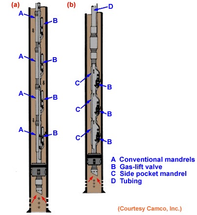
For conventional valves to be changed or serviced, the entire tubing string must be
pulled, while retrievable valves can be latched and set through tubing with a wireline
unit.