Showing posts with label Well completion stimulation course. Show all posts

Chapter 6: Corrosion and Erosion


Corrosion
Corrosion is defined as destruction of a metal by chemical or electrochemical reaction with its environment.’ It is reported that 80% of failures in production and pipeline operations are caused by corrosion.
 Corrosion may be apparent by metal loss, strength loss by cracking and solids problems
caused by formation of corrosion by-products. One of the first decisions in well completion design is the selection of the proper casing and tubing. Corrosion will not alter calculation of the tensile, burst and collapse, but it may dictate the selection of the grade of material necessary to satisfy these requirements. Corrosion is common in almost all hydrocarbon-producing environments and costs hundreds of millions of dollars throughout the industry every year.3 In addition, the economic problems are intensified through loss of revenues due to down time and deferred production. For corrosion to occur, there must be a circuit produced through which electrical current can flow. The circuit is called the corrosion cell and the electrical current produced by the process, although very small, can do enormous damage to metal systems. The basic cause of corrosion is instability of metal in its refined form. Because of the free energy relationship, the metals tend to revert to their natural state through the process of corrosion. Pure metals rarely exist in the natural world. To obtain a pure metal, a salt of the metal (the ore) is refined (energy added). This energy input is stored in the metal and serves as a source of potential (voltage) for the corrosion circuit. Since different metals require varying amounts of energy to refine, there are variations
in the amount of voltage available for the circuit. The following table from Patton5 is included to show the tendencies of metal to corrode. The half-cell potentials, which were reported by Peabody, were measured with a hydrogen reference electrode in a solution of the metal salt.


Galvanic corrosion occurs when the dissimilar metals are coupled in an electrolyte. The attack is from current flow within the simple “battery” formed by the metals and the water. Metals that are widely separated in the previous galvanic series will show the highest level of corrosion. Coatings on the metal surface, such as iron carbonates, block the galvanic current and lessen corrosion.
In any steel, the important sources of galvanic cell potential difference are:8
1. The various states of heat treatment of the steel, such as:
a. weld metal deposits,
b. the junction of weld and base metal,
c. tubing end heat treatment prior to upset (joint) manufacture
2. Cold Work and residual stress that result in anodes.
The Corrosion Circuit
The corrosion circuit requires an anode (the site of corrosion on the metal), a cathode, a metal connection between the anode and the cathode, and an electrolyte (liquid) surrounding the anode and the cathode.
Chemical Reaction
In acid solutions (pH e 7), reduction of hydrogen ions to hydrogen gas can be the dominant reaction in the absence of H2S gas. In neutral or basic soluiions (pH 17), reduction of oxygen is the dominate reaction. When gases such as CO2 and H2S are present, the reactions are modified by the gases. Presence of CO2 in neutral solutions can cause direct reaction of bicarbonate or carbonate ion with the steel. This can deposit a beneficial protective films such as iron carbonate. H2S on the metal surface stops the formation of hydrogen gas from hydrogen ions and permits a large percentage of the cathodic hydrogen ions to enter the steeL7 This is the start of one of the hydrogen embrittlements; cracking in hard steels or blistering in soft steels. As the metal corrodes, it dissolves at the anode and enters the solution as ions. It is an oxidation reaction since the iron leaves in an state. The electrons flow toward the cathode, where hydrogen gas is evolved. The schematic of the corrosion cell is shown in Figure 6.1 .5 The anode reactions are:


This reaction is for corrosion produced in neutral, agitated salt water.5 The actual location of the anode and cathode may vary with the inhomogeneities in the metal and attack may be localized or may occur over a very wide area. The rate of reaction is dependent upon many factors, including the salinity of the water, flow velocity, temperature, pH, metal alloy characteristics, and dissolved gases such as oxygen, carbon dioxide and hydrogen sulfide.
The overall corrosion process results in weight loss at the anode caused by the loss of iron and hydrogen embrittlement of high strength and highly stressed steels by penetration of the atomic hydrogen. The corrosion reaction is most severe where pits are formed. The intensity of the pitting is affected by the manufacturing, handling and production factors. In these areas, abnormalities such as large grains, poor heat treating, improper stress relief, mill marks, pipe wrench nicks, damage during running, and other factors contribute heavily to the location of electrochemical attack that causes pits. Endean summarized the common sources of metal corrosion as:*
1. Hydrogen sulfide - causes both pitting and general attack. The reaction product is a black, usually shiny mass and may be in the form of a hard scale or a finely divided solid dispersed in the water.
2. Carbon dioxide - attack is through pitting with brown or black reaction product. Pits produced in CO2 attack are frequently in a line and resemble a large cavity. The remainder of the pipe may be unaffected.
3. High concentration chloride brines with a pH of 6-7 produce shallow wide spread pitting attack similar to acids but much less severe.
4. HCI - mineral acid attack produces severe general pitting with frequent occurrence of deep channels and deep pits.
5. Sulfate reducing bacteria - SRBs produce a localized corrosion by trapping their own low pH waste product and protecting the corrosion from inhibitor contact. The location of the corrosion is usually under the bacteria colony.
6. Erosion damage - high velocity contact by fluids, gases containing mists and droplets, or fluids containing solids generates a smooth surface with frequent shallow channels, plateaus, and sharply defined transition areas, especially around the area of highest fluid velocity and directly across from perforation.
The amount of corrosion is often expressed as a mils (or thousandths of an inch) per year, MPY. This means of expressing corrosion is only usable when the corrosion rate is an even attack on the surface of the steel. Where pits occur, an MPY value is useless: generation of even a few deep pits can ruin a piece of equipment without loosing but the smallest fraction of a percent of the total metal mass. Rate of pit growth varies with the depth and size of the pit and the rate of penetration of the pit will actually increase with depth of the pit.2 As the pit is growing, the very bottom of the pit is the anode. This area becomes smaller with pit depth as the pit forms a V shape. The smaller bottom area looses metal at a faster rate to satisfy the current flow of the corrosion circuit. This is the reason for pin hole leaks in an
otherwise solid piece of equipment.
Acid Gases
The special case of production of hydrogen sulfide gas, H2S, carbon dioxide gas, CO2, or a mixture of the two is the area of acid gas technology.’O The corrosion produces one or more types of Hydrogen Embrittlement, HE, in the steel. Hydrogen embrittlement reduces the toughness of steel (a loss of ductility) and is most prevalent around existing defects (micro or macroscopic) in the steel. The steels most susceptible to hydrogen embrittlement problems are those with a yield strength of 80,000 psi, or greater (N-80 and higher alloys). In lower strength steels, hydrogen blistering is occasionally found. The corrosion caused by acid gasses is influenced by the pH and by pressure, temperature, the corrosion
resistance of the metal and the passive corrosion films formed on the surface of the metal.
Several forms of hydrogen embrittlements, HE, have been described including stress corrosion cracking
and stress sulfide cracking.’&’’
All forms of hydrogen embrittlement are brittle failures of a metal at a stress level below its yield
strength as a result of their exposure to atomic hydrogen.’’ The atomic hydrogen is generated on
metal surfaces by corrosion rea~t ion. ’T~h e hydrogen is diffused into the metal and causes a reduction
in the ductility of the metal. Sour gas increases the corrosion of HE by:‘’ (1) low pH of fluids that
contain H2S, (2) sulfide causes a greater percentage of the hydrogen created at the surface to enter
the metal, and (3) the anodic portion of the corrosion reaction tends to be localized, which helps
cracks initiate. The result of these actions is extremely rapid failure of some metals in sour fluids.
HE is generally associated with high strength steel and is common with H2S wells. The factors controlling
HE are:*
1. Steel yield strength - steel with yield strengths of 90,000 psi or lower (C-90, N-80, L-80, C-75,
etc.) are usually less susceptible to hydrogen embrittlement.
2. Hardness - Maximum hardness should be a Rockwell “C” scale of 22 or lower (the hard steels
are much more prone to attack from HE).
3. Stress level - At low stresses HE failures are lessened. In HE susceptible steels there is a
threshold below which HE will not occur. This threshold value is lowered for higher strength
steels.
4. Internal stress - The internal stress, which includes stored tensile stress produced by welding,
bending or surface damage is a common initiator for corrosion.
5. Hydrogen concentration - The time to failure of any high strength steel is a function of the concentration
of hydrogen.
6. Temperature - HE failures usually do not occur above 150°F. (A special exception to this is the
case of stress corrosion cracking7)
Two special cases of HE are sulfide corrosion cracking and stress sulfide cracking. Sulfide corrosion
cracking, SCC, causes a brittle failure of metals by the action of localized corrosion and stress.lg SCC
is normally encountered near the bottom of wells and in hotter environments than other forms of HE.7
In sour gas systems, SCC causes failure of high strength steels, all types of stainless, and many low
alloy nickel-based alloys.lg SCC will also occur in production of hot brines (chloride rich). SCC is common
in stainless alloys and materials. Alloys containing about 8% nickel are the most ~usceptible.~
Alloys with over about 42% nickel are usually immune to SCC.7 These alloys include Inconel, Incoloy,
Monel and Hasteloy. Other immune alloys may include cobalt-cromium-nickel-molybedenum alloys,
nickel-free low alloys, and nickel-free martensitic stainless steels.
There is a relationship between the environment and the metal to cause SCC; only certain metals will
crack in given environments at the critical stress level. SCC is considered to be an anodic process in
which a crack is initiated (usually by HE) and reaction progresses inside the crack. The dissolution of
metal at the tip of the crack controls the process. The environment inside the crack may be very different
from that on the surface of the casing due to the large area of metal and the protected environment.
The pH of the produced fluids, for example, may be between 4 and 6, while inside the crack, pH
may be between 1 and 2 (highly acid) because of higher concentration of chloride ions, which
increase the local corrosion rate.lg The overall corrosion rate of a material that is undergoing SCC
may be low and outer appearance may be good. However, the detrimental SCC corrosion in the crack
occurs as the result of the localized, often unseen, attack.
Stress sulfide cracking, SSC, occurs in high strength (high hardness) steels exposed to sour gas production.
It is also known as hydrogen stress cracking and hydrogen embrittlement cracking.20 SSC is
cracking that results from hydrogen charging (large volume entrance of hydrogen) of high strength
and/or high hardness steels. Most SSC occurs at lower temperatures and is prevalent in the upper
parts of the well. It may accelerate during periods of shutin or cool down, requiring only a reduction in
temperature to become active. SSC is a form of hydrogen embrittlement and is a bulk alteration of the
metal surrounding the surface areas.
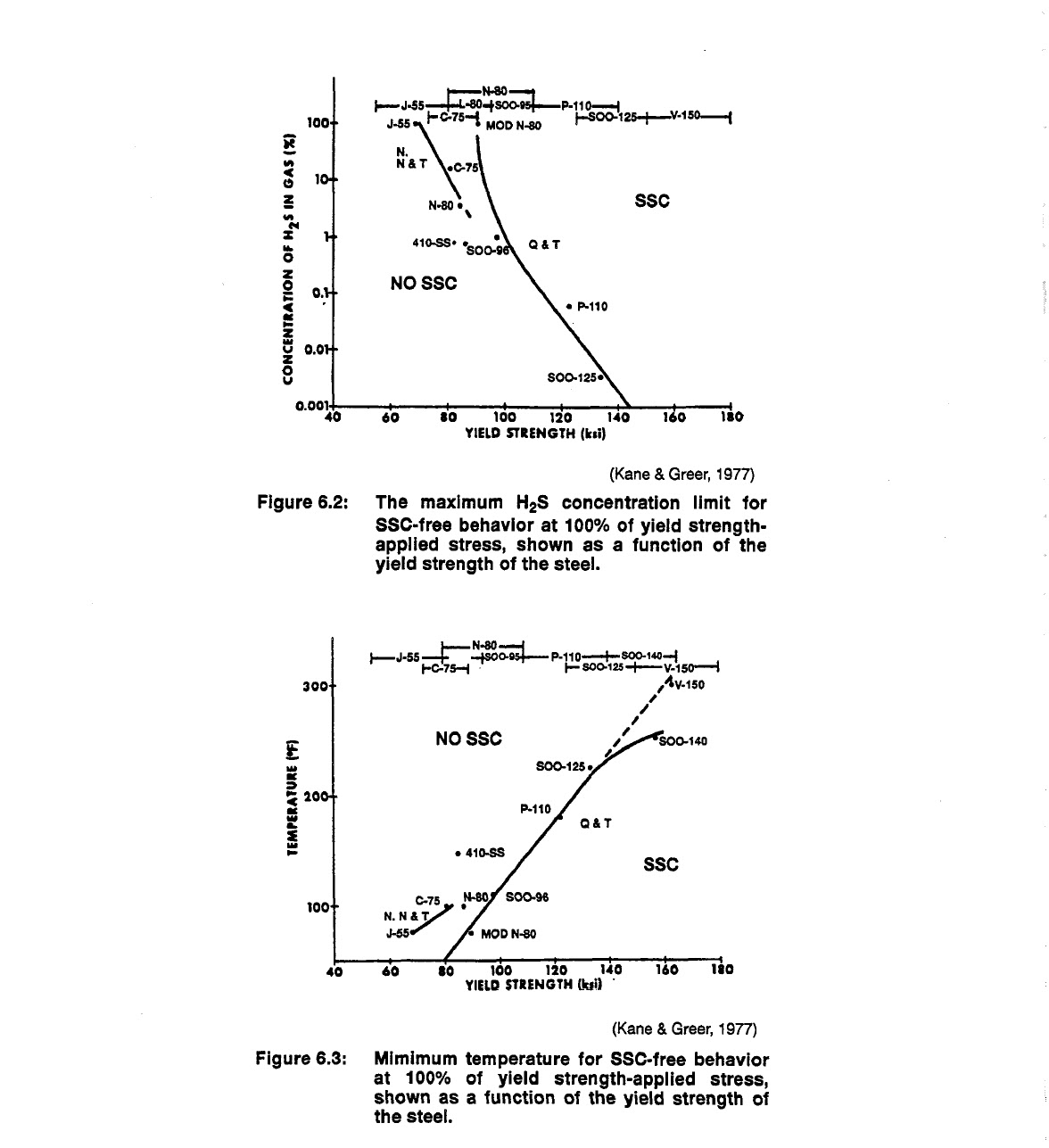
Most corrosion rates increase with an increase in temperature up to about 140 to 150°F. At this point,
several forms of corrosion are lessened and some corrosion inhibiting films begin to form. Although an
increase in temperature renders the steel more susceptible to attack by SCC, an increase in temperature
decreases the rate of stress sulfide cracking, SSC. At higher temperatures, the atomic hydrogen
that contributes to the initiation of the crack by embrittlement is able to diffuse out of the steel. Temperature
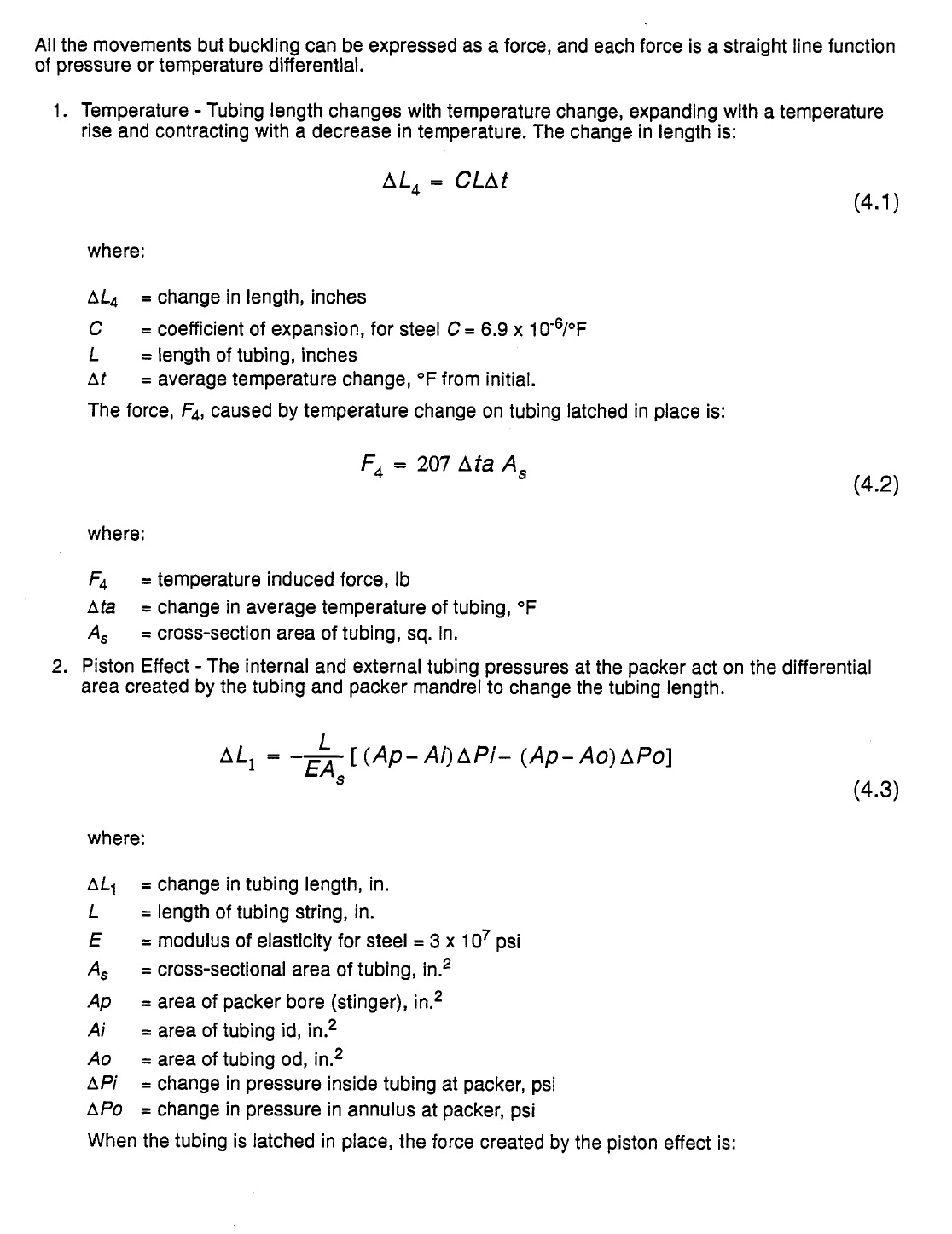
thresholds exist for SSC and above these limits, SSC does not occur. The limits for hydrogen
sulfide content and temperature are indicated in Figures 6.2 and 6-3. Figure 6.3 shows that the temperature
threshold for SSC free behavior is dependent upon the grade of steel. SSC can be controlled
with use of lower strength alloys.
Controlling Corrosion
Approaching corrosion control from a well completion position may involve selection of corrosionresistant
alloy,i1~i2*19*2’-24 films and coatings,2532 liquid
device^.'^^^-^^ The least expensive route will depend on the produced or injected fluids, completion
design and the level of protection required in the operation.

Modifying the produced fluid by changing pH or removing water or dissolved gasses such as oxygen,
CO2, or H2S are usually only available for use in pipelines and injection systems. Gas removal systems
such as gas stripping, degeneration and chemical treating may all be used to remove or reduce
the content of gases. Changing the character of the produced fluids is usually achieved by changing
operating conditions to control the separation of the condensing phase.

Coatings are a relatively simple and inexpensive way to isolate the metal (the anode and cathode)
from the electrolyte liquid. Permanent coatings include plastic, tars, cement and paint. Coatings are
usually chosen for a protection against a particular liquid. The plastic coatings, for example, include
resins and polymers that are resistant to low pH waters, oxygen, COs, or salts. Coatings are not resistant
to all influences however: acids, alcohols, and other materials will destroy some coatings. Care
must be taken in working over wells with coated tubing to avoid damage to the surface of the coating.
Abrasive action such as wireline action or coiled tubing are very detrimental. Damage to coated surfaces
offer sites for very localized, intense corrosion.
Liquid corrosion inhibitors act as temporary coatings or films on the surface and are effective in providing
a passive film or a coating if they are replenished on a regular basis. Selection and application
of inhibitors are critical elements in the corrosion control program of a well. There are literally hundreds
of chemical inhibitors for control of dozens of different corrosion problems on various types of
steels. The inhibitor for a particular application must be selected from lab or field tests at the conditions
where the corrosion will be active. Normally, these selection tests are started in the lab and completed
in the field with field trials on test metal coupons.
Complete reviews and comparisons of the methods of applying corrosion inhibitors are rare, but a few
case histories do exist. Houghton and We ~ t e rma r kh~av~e provided data on some corrosion problems
in the North Sea and compared the methods for application of corrosion inhibitors. In the wells that
were used for a database, average workover life was approximately 60-1 20 days. CO2 corrosion and
erosion were present in these wells’. Erosion was determined to have a significant influence on the
rate of corrosion and CO2 corrosion/erosion was found to be the normal mechanism of attack on these
wells.
During the study, the rate of corrosion for these wells was determined to be exponential rather than
linear. Once the corrosion started, very rapid increases in the corrosion rate were common. The most
prevalent place for attack of the corrosion/erosion was at changes in diameter or direction of the fluid
flow. The paper pointed out that sweet corrosion was prevalent in these wells even though there was
less than 14% formation water in the total produced fluids.
Ekofisk wells in the study that had a high GOR showed increased corrosion; probably by providing
greater volumes of CO2 and by increasing the flaw velocities of the produced fluids. The GOR has
also been shown to be a factor in corrosion in other studies. Even in gas wells, a change in flowing
fluid composition because of condensation of C-3+ hydrocarbons can result in a change in corrosion
intensity or location.40 The most common corrosion site depth was in the mid-range from 4000-
7000 ft. The mid-range location on these wells corresponds with gas breakout and increased turbulence
from suspended gas that is rapidly expanding due to the lowering of hydrostatic head.
In all cases of wells deviated more than 20°, a preferential attack along the low side of the tubing was
spotted. This attack reportedly resulted in troughs 1 in. wide that tracked along the inside of the low
side of the tubing.
This “pipe trough” development has also been though to be the result of a low oil wetting tendency of
the Ekofisk crude, which would result in a water wetted pipe. If the fluid velocity in these flowing wells
is below 2.5 to 3 ft/sec, the approximate minimum velocity for water entrainment in the oil, a free water
layer would exist at the lowest point due to gravity separation and increased corrosion could occur.8
The corrosion/erosion attack location was identified using casing calipers. Corrosion in caliper tracks
has also been observed. The cause may be that early caliper surveys were not followed with inhibitor
treatment to repair damaged protective films.
In the higher volume wells, preferential attack occurred on the pin-end shoulder on the coupling. The
shoulder seems to cause additional turbulence and pitting is a byproduct of the turbulence.
The paper reported a comparison of inhibitor treatment types, in terms of both economically application
and performance. Formation squeezes with inhibitor, continuous injection, and tubing displacements
were all examined. Continuous injection was found to be the least expensive in almost all flow
rates studied.
A second case study, and one that covers economics of chemical inhibitor usage was provided by
Akram and Butler.41 This work showed that the cost of the successful inhibitor protection program was
about $29,000 per well per year, compared with a super alloy tubular cost (for passive control) of
about 1.25 million. The cost of carbon steel tubulars for the same well was $271,000 (all dollar values
are 1982 U.S. dollars). The economic impact of the successful inhibitor program was significant;
34 years of inhibitor operation to equal the simple difference of super alloy and carbon steel tubular
cost. Obviously, the successful control of corrosion using either method depended upon good design
and strict application. All inhibitor films have to be replaced on a regular basis. While this addition is
relatively easy in injection wells by surface addition to injected fluids, it is more difficult in producing
wells. The inhibitor must be circulated into position and allowed to film on a clean surface without
being disturbed by action of other surfactants, inhibitors or solvents. Most inhibitors must be placed as
a dispersed phase in a non reactive fluid without the aid of surfactants. The application of these materials
may range from simple “dump” jobs down the back side (low pressure injection into the annulus
at the surface in a well without a packer) to periodic workovers requiring the well to be shutin while
inhibitor is injected down the tubing. Some wells are completed with a small string of tubing (1/4 in. to
1 in. diameter) down the outside or inside of the tubulars where the inhibitor and other treating chemicals
can be injected continuously.
Some naturally passive films (a reaction product of the metal and the wetting fluid) provide a barrier
surface that reduces the potential produced in the corrosion circuit by altering the reactivity of surface.
The film may be a metal oxide laye?5v27 or other reaction by-product that is not easily attacked by produced
fluid. These films are recognized as major corrosion controlling mechanisms. Corrosion of low
alloy steels at temperatures below 140°F, increase with the partial pressure of CO2 in the gas phase.
Above 140°F the corrosion decreases with temperature because of the formation of iron carbonate
and iron oxide films. The films are destroyed by acidizing or erosion during high velocity flow. In certain
cases, passivity is designed into the alloy by combining chromium and nickel with iron. Whether
these iron-chromium and iron-chromium-nickel alloys are active or passive depends upon the alloy
composition and the electrolyte. For example, in CO2 rich environments, 13% chrome alloys are successful
in preventing corrosion that destroys other alloys.25
Cathodic protection using sacrificial anodes or impressed current to offset the current of the corrosion
cell, can be applied to the outside of casing and pipelines and to the insides of production processing
vessels where a continuous water phase exists. It cannot be used internally in most production tubing
or inside pipelines.
Materials for Sour Service
The following description of materials for Sour Service is from Wilhelm and Kanelg and represents
generalized guidelines on selection of tubular components for hydrogen sulfide and carbon dioxide
service.
High strength tubular steel grades, often containing chromium and molybdenum designated for use in
H2S service include C75, L80, C90, and some specially processed C95. These materials exhibit necessary
resistance to SSC under some specific conditions for use in sour gas operations.
In general, the higher the yield strength of a material, the more susceptible it is to SSC. There are no
recognized carbon or low alloy steel compositions suitable for sour service at ambient temperatures
with yield strength in excess of 11 0,000 psi. The most widely used criterion for selection of materials
for sour service is hardness. NACE requirement MR-01-75 specifies that for steels to be considered,
they must have a hardness value below HRC-22 (some exceptions to HRC-26).4
Stainless steel casing (greater than 12% chromium) are used when superior resistance to general corrosion
is necessary. Table 2 shows composition of several of the high nickel alloy materials. The
steels increase in cost as corrosion resistance is increased.
The following paragraphs, also from Wilhelm and Kane,lg describe the general classifications of the
high strength alloys available for use in corrosive environments. Stainless steel is a generic term for a
group of steels having a chromium content of over 12%. Most metallurgists refer to the stainless steels
with the more widely based term “corrosion resistant alloy,” or CRA. The general classes of the alloys
are listed in order of increasing resistance to SCC and SSC (also increasing cost).
1.
2.
3.
4.
5.
6.
7.
Martensitic stainless steels, (11 -1 8% chromium) have applications in wellheads and tubing
where high yield strengths are not required.
Precipitation hardened stainless steels (12-1 8% chromium and 6-1 2% nickel) are useful for
downhole equipment or tools that require non-cold-worked, high yield strength materials. Some
of these materials, depending on composition, may be susceptible to SCC and SSC.
Duplex stainless steels (22-28% chromium and 5-7% nickel) have a resistance to chloride cracking
that exceeds the resistance of low alloy austenitic stainless steels, but they may be susceptible
to SSC or SCC in the presence of H2S.
Low alloy austentinic stainless steels (1 8% chromium and 10% nickel) offer better resistance to
SSC than martensitic stainless steels, but yield strengths are limited. These alloys are susceptible
to SCC and pitting by chlorides.
High alloy austentinic stainless steels contain 20-30% chromium and 20-35% nickel. They
achieve strength through cold work and offer the best combination of corrosion resistance and
mechanical properties of all the CRAs. The cost for these alloys is high.
Nickel-based super alloys such as C-276, 71 8, and MP35N (cobaltlnickel-based) have better
resistance to H2S than most other types of commercial alloys but may be extremely expensive.
They do have the advantage of very high yield strengths.
Titanium alloys are slowly being introduced to the industry although the use is rare at the present
time.
CO2 Corrosion
CO2, one of the acid gases, is a very common contaminate in gas, oil and water production, even in
sweet reservoirs. CO2 corrosion of steel is usually a localized corrosion that takes the form of pits of
various sizes. Liquid water is necessary for CO2 corrosion to take place.43 The typical corrosion product
of the CO2 reaction is ferrous carbonate.a Dissolved carbon dioxide content is a function of pressure
and temperature and pH is much less important. Corrosion increases for increasing carbon
dioxide content.
Pitting produces severe penetration. Outside of the affected areas, the corrosion rate might be limited
and the transition from an affected to an unaffected area can be very abrupt. The action of CO2 attack
has been described as both chemical and physical through e r o ~ i o nE.ro~s~ion~ c~an~ a ccelerate the
overall corrosion rate by a hundredfold or more by removal of protective scales, oxides and corrosion
inhibitor films. Even for CO2, however, the increase in rates usually is in the area of five to ten
The addition of CO2 gas to water can reduce the pH to a value below 4, promoting acid attack. CO2
corrosion from chemical attack has been generally effectively controlled through the use of 13%
chrome tubulars.
Although CO2 corrosion and stress sulfide cracking have nothing in common when both corrosion factors
are present in a well, control of both forms of corrosion may be accomplished by using a corrosion-
resistant alloy to block CO2 attack and a reduced hardness to prevent SSC. Choosing a 13%
chromium steel that has a hardness below 22 Rockwell hardness-C, (LSO tubing), should also be
effective.
One severe drawback to using the 13% chromium steels is that they exhibit very limited resistance to
pitting during storage where air and chloride are present (seacoasts). This type of corrosion can much
more significant inside the pipe, particularly if condensation inside the pipe forms standing puddles.24
In the well, control of pitting corrosion of the 13% chrome steels relies on the deaeration of water.
The second type of severe corrosional effect produced by CO2 is largely physical -the erosional effect
produced by changes in fluid flow direction or an effect often described as ~ a v i t a t i o n . ~E~ro*si~on~ is* ~ ~
the increase in the rate of metal deterioration from the abrasive effects of a fluid flowing into or
through a pipe. Other sources of erosion may include entrained gas in liquids, liquid droplets in gas,
solids in any fluid, very high flow rates, or any restriction in the completion strings that causes a drastic
change in the flow velocity of the produced fluids. Erosion may often lead to a removal of the effective
inhibitor, corrosion film, or reactant film. Severe cases can be identified by grooves or rounded
pits or holes that are usually smooth and lie along the direction of flow. Removal of a protective inhibitor
or corrosion oxide film takes place when the strain on the film or corrosion oxide layer exceeds the
strain for the failure of the film. Erosion by solids and droplets may also affect the tenacity of the film
on an exposed surface. The failure of a corrosion oxide layer takes considerably longer than the failure
for most film-forming materials.
Squeezing or continuous injection of inhibitors may not be cost effective if the completion string ID is
smaller than the minimum ID required to prevent erosion. If this principle is violated, the film may be
continuously stripped off, even at high loading rates. Not all inhibitor films react in the same manner to
stripping by erosion; a few products offer very good performance in high velocity applications.
Other Factors
The presence of oxygen either as dissolved or entrained gas substantially increases the corrosion,
Figure 6.4.2 In almost all fluid handling systems, oxygen must be removed prior to injection of water or
shipment of the fluids by pipeline.
The pH of the water and the velocity of the water influence the corrosion attack. The chart in
Figure 6.5 illustrates the relative corrosion of flowing and nonflowing fluids versus the fluid pH. The
velocities shown in the graph are for water velocities of 3 to 7 ft per second. Below 3 FPS, corrosion is
reduced at pHs above 7. Notice for the flowing case that there is very little corrosion in waters with a
pH above 7 (basic). In these high pH waters, iron is almost insoluble, so the byproducts of a corrosion
reaction cannot be swept away from the corrosion site and the corrosion reaction is stopped.
The amount of water in the production is also a factor in corrosion. Water cuts below 25% are likely to
cause less corrosion than water cuts above 45%, especially at pHs below 7. As water cut increases,
the tendency for a steel surface to be oil wet decreases. Corrosion is very low for most oil wet surfaces
and very high for most water wet surfaces. Since most wells are at least very slightly deviated,
the water caused corrosion damage may be confined to a trench in the low side of the pipe. In wells
where the flow rate in the tubing is not high enough to keep all the liquids moving at near the same
velocity, the water may reflux (up and down with gas rate changes) in the low side, creating a serious
corrosion trench even at very low water cuts. Inspection with caliper or electromagnetic surveys (measures
metal loss through field generation and interruption techniques) can usually spot the trench if
one exists. Water can be produced and carried as an emulsion (entrained water) at flow velocities of
3-1/2 to 5 fps.

Corrosion by Stimulation Acids
The use of stimulation acids such as HCI and HCVHF create severe problems in the specialty tubulars.
Special problems of selective effects of inhibitor^,^^ pitting and intergranular attack,47 detrimental
influence of added organics,48i49 and increased corrosion of the fluoride ion,50 require special inhibitors
and special inhibition techniques for the high allow steels. The primary attack of the steels by acid
is severe pitting and intergranular attack that is difficult to control with inhibitors. Localized pitting may
be severe enough to ruin a section of the string.
Acid inhibitors work in the same manner as other corrosion inhibitors; by filming and passivating the
surface. The HCI and HCVHF acids are much more severe environments than other types of corrosion
and the inhibitors for these uses are specially blended and have much shorter effective life spans.
Also, presence of mutual solvents, alcohols,
destroy the effectiveness of some inhibitors.
oil solvents and surfactants in the acid may alter or
Some of the expensive super alloys, such as the 13-chrome materials, may be especially sensitive to
HCVHF acid attack and special inhibitors are required.
Destruction of Elastomers
The steels used in the tubulars and well equipment are not the only materials susceptible to corrosion.
The elastomers (plastics and rubbers) used in the seals are also affected by the well fluids and must
be carefully selected to avoid problems. The attack on elastomers by gas is usually by swelling or blistering,
5’ both involve invasion of the elastomer by the gas. Rapid release of the pressure around a
gas permeated seal will likely cause explosive decompression and destruction of at least the outer
layer, the sealing edge, of the seal. Surprisingly, although gas permeation of a seal can destroy the
seal when pressure is released, the seal may function adequately before pressure release. Reaction
of various liquids to elastomer seals depends on seal type and position, temperature, liquid type, pressure,
previous seal contamination and the presence of some lubricants used for tool assembly.52 In
general, nitrile seals are used for most general purpose applications where oil contact is necessary.
Other compounds such as the fluorinated elastomers (e.g., Viton) are available for contact with aromatic
solvents (xylene and toluene). Other specialty compounds are available for specific, highly corrosive
conditions or contact with powerful solvents; however, seal cost increases quickly with the more
exotic elastomer compounds. Some metal-to-metal seals are being offered where elastomer destruction
is most severe.53
Microbial Corrosion
Microbiologically influenced corrosion (MIC) active corrosive influence of the attached (sessile) bacteria
c o l o n i e ~ . ’T~h*e~ p~ro blems are two fold; the colonies cover areas of steel, blocking corrosion
inhibitors from reaching the pipe surface, and the waste products of the colonies are often very corrosive
in the protected areas under a colony. The sulfate reducing bacteria, SRBs, are the most detrimental,
with the capability of souring wellbores and parts of reservoirs with H2S. Bacteria are
controlled by cleaning the water and treating with bactericides.
Nonmetallic Tubulars
As an alternative to steel casing with its problems with corrosion, fiberglass casing, tubing and rods
are being applied in some ~ e l l sTh. e~ ad~va~nta~ge~s o f the plastic materials are excellent resistance
to most forms of water related corrosion and some scale and paraffin deposition. Most applications
have been in shallow, low pressure wells, where high strength is not needed; however, new placement
techniques and plastic formulations are stretching limits of application.
Predictive Techniques and Inspection Devices
Monitoring the rate of corrosion is of critical importance to determine when to repair or replace equipment
and to judge the effectiveness of corrosion control techniques on well e q ~ i p m e n t .A~ s~y-s~te~m -
atic examination of the produced fluid chemistry, operating conditions and failures can describe the
potential for further failure.55 Monitoring of corrosion in the well uses several logging techniques to
monitor abrasion (and other wear), pitting and surface corrosion.
The data from produced fluid analysis includes ion analysis, pH, gas type and content. It can be used
with computed based predictive models to establish a general potential for corrosion in the well. Corrosion
coupons inserted into the well stream can verify the predictive results and help evaluate the
effect of an inhibitor. Sections of test pipe are also used, normally in surface piping, to evaluate
selected metals.
When a corrosion related failure occurs, it is most important that the cause of the failure be determined.
The analysis of corrosion products and the characteristic corrosion pattern can usually determine
the type of corrosion that caused the failure. Hardness tests, microscopic examination, and
chemical analysis of the failed and unaffected surfaces are also tools of identifi~ation.~~
To monitor the corrosion rate and general condition of the tubulars in the well, a set of instruments are
used that provide data for comparisons with earlier readings to arrive at a corrosion or erosion rate.
These tools include multifingered c a l i p e r ~p,r~ob~e s for measuring anodic activity,57 induction tools to
measure pipe mass,58 magnetic devices,59 sonic tools that measure pipe thickness,60 and some
experimental tools that locate cracks in the pipe.60 These tools will establish a rate of corrosion or
wear when the results from several regular runs are compared.
Erosion
Surface erosion from solid particles in a high velocity produced fluid stream is normally associated
with unstable formations such as unconsolidated sands. Other occurrences of erosion include cases
of choke and tree loss following rapid back flow of wells after fracturing. The common denominator is
the high flow velocity.
Maximum velocities that can be tolerated in a situation will depend on the flowing fluid and other factors
including foaming or emulsifying tendency, solids and entrained gas. Mechanical limitations in the
piping design or metering apparatus may also influence the maximum permissible flow rate.
Although some information exists that a corrosion inhibitor film is removable by high velocity flow,2i61
other authors offer evidence of successful inhibitor film performance at mass velocities of up to
100 Wsec with abrasion where inhibitor was continuously present.62 In any design where flow rates
will be high, a testing program should be used to identify the best method of corrosion protection.
The concept of critical velocity for flow of fluids with no solids in sizing of piping is covered in API RP-
14E.63 In general, the limits for dry crude flow velocity in pipe is about 30 to 35 fps (ft per second) and
for wet crude, the maximum velocity is 20 to 25 fps. At faster flow rates, some steel may be lost to
abrasion from the clean liquids. In some inhibitor protected systems, the limit of fluid velocity is often
much higher than set by the API equation.

The erosion rate of any metal surface is strongly controlled by the presence and hardness of naturally
occurring (but metal-composition related) oxide or sulfide film. This film, which depending on composition,
can be much harder than the pure metal surface, is one of the main factors that reduce erosion
(and some forms of chemical corrosion).

Presence of mist droplets in the stream can destroy the natural or added inhibitor barriers and rapidly
increase corrosion. Actual abrasive induced failures of the pipe depend on the entrained droplets or
solids in the gas as well as the density of the gas. Estimates of the densities and good design velocities
are contained in Figure 6.6. For further information, refer to the “Oil Field Corrosion Detection and
Control Handbook,” by Endean, available from Champion Chemicals Inc., Houston.

The API RP-14E equation is a quasi-rigorous attempt to determine critical velocity for general purpose
projects. Craig 68 proposed flow ranges for a modification of the RP-14E equation, proposed by Griffith
and Rabinowicx (1985), where the C factor was calculated. The calculated value of C was based
on actual well conditions. The equation was only very slightly different:

but the C was dependent on flowing fluid and pipe metallurgy, rather than a range of operating constants.
When using chemical resistant alloys such as stainless and some nickel based materials
(especially those containing Chromium), the stable range of the C factor in the equation would be in
the range of 160 to 300. The 160 to 300 range for CRA tubulars is well proven infield performance for
long lived projects.
The ultimate value of C is then dependent on alloy composition, oxide or sulfide layer composition,
and flowing fluid composition (H2S, CO2, etc.). The layer composition and fluid resistance would also
change with temperature and impact resistance. Craig proposed a further modification of the equation
to allow input of the oxide hardness layer

where P is the measured hardness of the oxide layer in kg/mm2 and p is fluid density in Ib/ft3. The use
of such an equation for calculations is limited at the present time by available data on hardness, P.
Craig offers the following explanation: “for Ti alloys, using a hardness of 1,000 kglmm2 for titanium
dioxide (Ti02) film formed on the alloy, the C factor would be 189. However, if aluminum oxide (aI2O3)
were incorporated into the oxide of any alloy so it was the predominate film, then P E 200 kg/mm2 and
C = 255. Conversely, if a SS or Ni-based alloy containing Cr is exposed to a high H2S environment,
then the film could be predominately Cr2S3, with P - 480 kg/mm2 and C would drop to 138l (with data
from A.A. Ivan’ko - Handbook of Hardness),
Impingement of particle laden fluids on a screen, casing wall, choke, or other surface in the well will
result in some erosion, regardless of the velocity flow. Erosion is usually only severe however, when
the fluid flow velocity is high enough to impact the solid particles on the surface with enough force to
abrade the metal or the natural or man-made coating on the metal surface.
Well completion decisions in wells with solids erosion problems may take one or more of three routines:
(1) decrease the flowing liquid velocity with larger perforations, larger wellbores and larger tubing,
(2) use hardened blast joints to slow the rate of erosion, and (3) control the solids with gravel
packs and screens.
If the erosion problem is slight, blast joints represent the cheapest methods of control. If erosion is
severe, the producing pays are usually gravel packed.
The erosion rate of any surface exposed to fluids that contain solids depends on the size, roundness,
and composition of the solids, the amount of solids in the flow stream, the velocity of the flowing fluid,
the shape of the flow path and the hardness of the metal layer exposed to the fluid. The worst erosion
conditions are created when sand grain sized (0.01 to O.l”), particles of high density materials rapidly
strike the metal surface at angles of about 45” to 95”. If the energy of the impact is sufficient to dislodge
or break the oxide layer, then erosion and some forms of corrosion will be accelerated.

Chapter 5: Well Heads, Chokes and SSSVs lec ( 14 )


Well heads
Wellheads are the connection point for the tubulars and the surface flow lines as well as being the surface pressure control point in almost any well operation. They are rated for working pressures of 2000 psi to 15,000 psi (or greater). They must be selected to meet the pressure, temperature, corrosion, and production compatibility requirements of the well. There are three sections of a wellhead, and each serves a function in the completion of a well.’ The outermost cemented casing string, usually either the conductor pipe or the surface string, is fitted with a slip type or threaded casing head. The head, Figure 5.1, also called a well head flange, supports the BOPs during drilling and the rest of the well head during production. A port on the side of the head allows communication with the annulus when another casing string is run. For all additional casing strings, a casing spool is used. The spool has a flange at each end. The flange diameter, bolt pattern and seal assembly are a function of the spool size range and the pressure rating. When specifying well head equipment, all pieces should be rated for the same pressure. The tubing is hung and isolated in a tubing spool. The tubing is “spaced out” to come to the right height for the seal assembly by the use of pup joints (short pieces of tubing). Annulus communication is provided in the ports on the side of the spools.

Each spool has alignment screws for aligning the tabular in the center of the spool. Alignment is critical since each flange connection (bolt hole alignment) depends on the last casing being in the center of the spool below it.
Multiple tubing strings can be accommodated by special heads. These head designs depend on isolation seals in the well head and multiple tubing spools. Setting the tubing and casing strings in tension is a common practice to offset the effects of buckling created by tubing expansion when hot fluids are produced The seal between each section is a single metal ring that fits in grooves in the top and base of connecting spool sections. The pressure to seat these metal-to-metal seals is provided by compression when the section flanges are bolted together. Oil is applied to the seals before bolting down the flanges. Various methods and devices for sealing have been tested for seals. Elastomers are subject
to attack by solvents2 and temperature ~ y c l i n gM. ~e tal to metal seals are the most common, especially in severe service areas. In sour gas (hydrogen sulfide) areas, special metals are often needed for wellhead. The final section of the wellhead is the familiar “Christmas tree” arrangement of control valves. The tree sits on top of the tubing hanger spool and holds the valves used in well operation, Figure 5.2. The master valve is a full opening valve that is the main surface control point for access to the tubulars. It
is always fully open when the well is producing or when a workover is in progress. The working pressure rating of the master valve must be sufficient to handle full wellhead pressure. If a valve or fitting in the upper part of the tree must be replaced, the master valve can be closed without killing the well (for all wells with a clear tubing, i.e., no rods). On very high pressure (P, > 5000 psi) or hazardous wells, there may be two master valves; a backup for insurance against leaks in the main valve. The wing valve (often two valves) are mounted immediately above the master valve in a separate spool. Produced fluids leave the wellhead at the wing valve connection. The purpose of multiple wing valves is to allow changing of chokes or flow line repair without interrupting well flow. The swabbing or lubricator valve is mounted above the wing valve and is used to open the well to entry by a tool string. A schematic of the wellhead and tubulars is shown in Figure

The choke is the only device used to limit the production of flowing fluids. Using a valve, such as the wing valve or master valve, to limit fluid flow would allow fluid flow (possibly with solids) to cross the sealing surface of the valve. This could lead to erosion and a leaking master valve and would require killing the well to replace the valve.


A connection on top of the swabbing valve can be used to mount a lubricator. A lubricator is a pressure rated tube that allows a tool string to be lowered into the well, even while the well is flowing. One end of the lubricator is attached to the swabbing valve and the other contains a seal assembly that seals against the wireline that is used to run the tool. Since the lubricator stands straight up to allow the tool string to drop into the well, the length of the lubricator (and the length of the tool string) is controlled by the length of lubricator tube that can be safely supported by the equipment on location. A more detailed discussion of the lubricator will be given in the chapter covering wireline techniques.
Subsea Wellheads
A special type of well head is involved in a subsea well. In subsea wells, the wellhead sits on the ocean’s bottom at depths from less than a hundred feet to over 2500 ft. Access is much more difficult than in a surface well, thus subsea completions require a well to be low maintenance, usually a sweet gas or flowing oil well. The wellheads for these wells must be self contained units with controls that can be manipulated by remote action at the well head by a ROT (remotely operated tool), by diver or by ROV (remotely operated vehicle). Almost all subsea operations, including drilling, begin after a template is installed on the ocean floor. The template serves as a locator for almost all tools used to drill, complete and workover the well. A schematic of the template and several workover and completion “tools” are shown in Figure 5.4. The modular work devices in the figure are characteristic of a surface wireline assisted operations. The production well head that fits into the template must provide the
same solid connection to the well as all land based well. Because of the remote or diver operation, however, appearances are vastly different than a surface well. Replaceable components of the wellhead such as valves and chokes are often equipped with guide bars to assist in remote replacement.


Coiled Tubing Well Heads
The use of coiled tubing for recompletion and even initial completion of some wells requires the use of special hangers or even complete wellheads that are designed especially for coiled tubing. Coiled tubing is being used in place of conventional tubing in some wells to minimize rig cost or to avoid killing the well to run tubing. Because of the lack of connections, coiled tubing can be run through stripping rubber seals in the BOP or through a standard stripper head. Hanging the tubing off in the wellhead requires slips; and, in live well workovers, these can be attached to the tubing and snubbed through the BOP stack to the slip bowl portion of the wellhead, or the slips can be made a part of the wellhead
and activated from outside. Coiled tubing completions may incorporate well ore bolt-on components or may be completely spoolable including gas lift valves, SSSVs and packers.
Examples of a hanger element are shown in Figure 5.5 and 5.6. These heads require a setting point below the master valve for a workover where the wellhead is nippled down. For low cost recompletions where the existing tubing and wellhead will not be removed, the coiled tubing is set through the existing master valve with the coiled tubing hanger and a new master valve set above the old master valve. Success of the coiled tubing completions and recompletions has been good when the tubing is sized correctly for the well condition.

Hydrate Control in Coiled Tubing Completions

Coiled tubing offers very good opportunities for recompletion or even initial completion of some wells, however, coiled tubing is particularly susceptible to collapse and compaction from production forces if an ice plug or hydrate plug forms either in the tubing or around the tubing. Problems in some operations where ice plugs have formed in the annulus during flow have caused sufficient force to collapse and compact coiled tubing to the point where 30-40 ft of coiled tubing are compressed into an area only 5 or 6 ft long. The only way to prevent ice plugs is either to control the rate of the gas flow so that the temperature drop during gas expansion does not create ice plugs or to inject a freeze inhibitor below the hydrate point to totally inhibit the formation of the ice.

Example: Wellhead configuration - For a gas producing formation at 9600 ft with a reservoir pressure gradient of 0.55 psi/ft, what is the minimum wellhead equipment pressure rating (in psi) needed to cover production or fracture stimulation with an 8.5 Ib/gal frac fluid, when fracturing the zone at 9600- 11 000. The friction pressure down the 4-1/2 in., 12.6 Ib/ft, N-80 work string (packer set at 9300 ft) during the frac will be 75 psi/lOOO ft of tubing length. During production flow the friction pressure is 10 psi/lOOO ft. Shut in during production will be with a full column of gas (0.1 psi/ft). Standard safety factor for well head working pressure is 80% of rated capacity.
Solution: Calculate highest possible surface pressure.
1. Max producing pressure (shut in with gas column) = (9600 x (0.55-0.1) = 4320 psi
Don’t use the friction pressure on producing since the worst production surface pressure case is static with gas in the tubing.
2. Max fracture stimulation surface pressure = (0.83 x 9600) - (9600 x (8.5 x 0.052)) + (9.3 x 75) (7968 psi) D (4243 psi) + (698 psi) = 4423 psi
Minimum wellhead pressure rating 4423/0.8 = 5529 psi
Chokes
Chokes hold a backpressure on a flowing well to make better use of the gas for natural gas lift and to control the bottomhole pressure for recovery reasons. In vertical pipe flow, the gas expands rapidly with decreasing hydrostatic head and the liquid moves in slugs through the tubing. The potential gas lift energy is rapidly lost and liquids fall back and begin to accumulate over the perforations. Accumulating liquids hold a back pressure on the formation. If enough liquids accumulate, the well may “die”
and quit flowing. A choke holds back pressure by restricting the flow opening at the well head. Back pressure restricts the uncontrolled expansion and rise of the gas and thus helps keep the gas dispersed in the liquids on the way up the tubing. Chokes may be variable or have a set opening, Figure 5.7. The set openings, often called “beans,” are short flow tubes. They are graduated in 64th~ of an inch. Common flow sizes are about 8 through more than 20 (in 64th~f)o r small to moderate rate gas wells. Liquid producers and high rate gas wells us 20+ choke settings. The size of the choke needed depends on reservoir pressure, tubing size, amount of gas, and amount and density of liquids. Variable chokes may use a increasing width slot design that allows quick resetting. They are useful on well cleanups following stimulation where choke size can vary over the course of a single day from
4/64ths to over 40. They are also used where periodic liquid unloading necessitates frequent choke size changes.

Solids in the produced fluids are the major source of failures for chokes. Abrasion from sand, scale, ice, corrosion particles and other solids can cut out the choke restriction and cause the well to load up with fluids and die. Choke abrasion from solids and cavitation is increased when large pressure drops are taken. In these situations, choke life is often measured in minutes. For better performance at high pressure drops, take the drop in stages across three or more choke sets in series. The problem is with gas expansion; as gas goes from 5000 psi to atmospheric pressure, the gas expands 340 fold, with a
similar increase in velocity. The same pressure drop, taken in series from 5000 to 3000, from 3000 to 500 and 800 to atmospheric results in gas volume (and velocity) increases of 136 fold (5000 psi to 3000 psi), 150 fold (3000 psi to 800 psi) and 54 fold (500 psi to atmospheric). The 340 fold total drop is the same, but the velocity increase across any one choke is significantly reduced.
Subsurface Safety Valves
When a well head is damaged, through accident or even terrorist incident, the fluids from a producing well can continue to flow, creating pollution and safety problems. One solution to the wild well potential is the use of safety valves. Safety valves are used to automatically halt the flow of fluid from a well in the event that the surface equipment of the well is damaged. Safety valves located at the surface are surface safety valves (SSVs) and those located below the wellhead are subsurface safety valves
(SSSVs). SSVs are located above the master valve and below the choke and/or beyond the choke on the production line. SSSVs are located in the tubing string below the ground or mud line. Together, the surface safety valves and subsurface safety valves form a redundant system of fail-safe valves. The valves are designed to be fail-safe; they are designed in a normally closed position. Opening of the valves requires application of a pressure to the valve to hold the valve open. When the pressure is lost, all safety valves close automatically. Safety valves are typically used offshore, in environmentally sensitive areas and in some remote locations on unattended wells. Any requirement for a subsurface safety valve and the depth of the valve below the wellhead depends upon the application and local government requirements. In offshore U.S., SSSVs are required and the subsurface safety valve is usually set in the tubing string 100 ft or more below the mud line. In the event of an accident or disaster, in which the wellhead equipment is partially or completely damaged
or removed, the valves will shut in the wells and prevent pollution and fire. The pressure that keeps the safety valves open is supplied by a small pump in a hydraulic-controlled panel on the surface platform.12 The pump is an automatic hydraulic supply unit, powered usually by
clean gas pressure. The pump supplies the control line with a 7 Ib/gal clean hydraulic oil at a set pressure. Other types of actuation systems that have been tried for control of the SSSVs include differential flowing pressure,’0 electric downhole solenoid,” velocity actuatedIg gas,l3 electromagnetic wave control (directed through the sediment^)'^-'^ and through loss of tension in the tubing string. The earliest valves were designed to close if the well flow reached some maximum rate and were used almost exclusively offshore. The idea behind the design was that the valve would close if the platform was damaged in a storm. The problem with this type of downhole “flow sensitive” control, was that the valves were continually in need of resizing as the well’s production capacity declined (reservoir
depleted). The maximum rate trigger-mechanism was also a nuisance when high rate flow of gas was needed to meet market demand or when liquid slugged through the tubing. SSSV control is now almost exclusively from the surface via a small hydraulic control line on the outside of the tubing. If the pressure supply is interrupted, the valves closes automatically. The valve sealing mechanism varies with manufacturer and the age and type of the valve. Most SSSVs use either a flapper valve or a ball valve with the current favorite being the flapper. The seat and flapper unit are protected from the well stream by a spring opposed sleeve that slides through the open flapper and isolates both the seat and the flapper. The sleeve is held in place by the hydraulic control pressure. The flapper assembly may be elastomer seal, metal-to-metal or a mixture of the two systems. Metal-to-metal seal units can be built for pressures in excess of 25000 psi. Ball valve units are equipped with spring loaded mechanisms that rotate the throat out of the well stream when the
hydraulic opening pressure is removed. Examples of flapper and ball valves are shown in Figure 5.8. Other types of seal mechanisms have also been tried.

The two conveyance types of subsurface safety valves are tubing retrievable and wireline retrievable. Tubing retrievable valves are run as part of the tubing string (the valve body is made up as part of the string) whereas wireline retrievable valves can be run and retrieved from a profile set in the tubing string. In the U.S., the tubing retrievable valves ars almost twice as popular as the wireline retrievable valves, while in non-U.S. areas, the wireline valves are more popular than the tubing retrievables. The reasons for the popularity differences are found in personal preferences, workover cost differences and, to some extent, in regulations regarding well operation. The benefits of the tubing retrievable
valve is that it has a fully opening bore, with very little obstruction to the flowing fluids. One disadvantage is that if there is a problem with the valve, the tubing must be pulled to the depth of the valve for service. This requires use of a rig; a large cost for many remote platforms. The tubing retrievable valves also require a relatively large upper casing section because of large valve body. The large outer body diameter (over 7 in. for a 4-1/2 in. bore valve) is necessitated by the flapper, spring and pressure equalization equipment within the valve. The wireline retrievable subsurface safety valve can be replaced by wireline without pulling the well, but it restricts the opening through which fluids may flow. The flow restriction for this type of valve may reduce 4-1/2 in. tubing to about a 1-112 in. bore over the 5 to 6 ft length of the valve. For most wells, this is not a severe restriction over a very short length. In wells that produce paraffin or scale, however, this flow restriction, especially near the top of
the tubing may serve as the site for solids deposition and promote rapid valve failure. In wells that produce sand, any restriction may be a site for abrasion. In wells that do not precipitate or produce solids, the valves are often a good choice, especially in areas where well deliverability rate is critical and time consuming workovers (such as pulling the string to replace a tubing retrievable SSSV) must be avoided. Wireline retrievable valves must be set in a special profile that is made up as part of the string. The profile seat is connected to the same type of external control line that is used for the tubing retrievable valve. A set of seals on the outside of the wireline valve isolates the hydraulic pressure port in the profile and allows a connection to the valve control mechanism. If the valve fails or malfunctions,
the wireline unit can be removed and replaced by a low cost wireline operation with minimum productivity interruption. Safety valve failures are rare but have been documented. When a valve fails to close, it is classified as a failure. When a valve fails to open, it is classified as a malfunction. The difference between the two labels comes from the design intent of the valve. Since the valve is designed to close when surface control pressure is lost, a failure is failure to close. Either event is troublesome. One study on the reliability of SSSVs, showed the valves to have a failure rate that was on the order of 0.8 to 2.3% in normal operations.16 One of the biggest reasons for SSSV failure (of valves tested) is
plugging of the sealing mechanism with paraffin, scale, produced sand, ice and other ~ o l i d s .It~ is, ~ ~ ~ ~
very important to operate the valves periodically so debris can be removed from the assembly and that valve’s internal mechanism can be lubricated. This operation is known as “exercising” the valve and is recommended to be done once per month. To exercise the valve, the wing vent is usually closed to shut the well in and the safety valve is open and closed several times. Merely releasing and restoring the hydraulic pressure at the surface will not confirm that the valve has actually closed. After the hydraulic control pressure is released, a few hundred psi can be bled off the tubing at the surface. If the pressure does not come back to initial shut-in pressure, then the valve is sealing. The amount of
pressure that needs to be bled off at the surface depends of what seat material is in the valve. Elastomer seals are tested at about 500 psi while metal-to-metal seals are usually tested at least 500 to over 1000 psi. The recommended test pressure is available from the valve manufacturer. A regular maintenance schedule may be a legal requirement of ~peration.‘~-’~ Reliability of the valves is very good if precautions are taken on regularly “exercising” the control mechanism. All of the 36 wells on the ill-fated Piper Alpha platform in the North Sea were equipped with SSSVs as per regulations. After the platform was destroyed, the fire was caused by the uncontrolled volume of produced gas in the pipeline (nearest shutoff was reportedly 1-1/2 miles away). The fire-fighting crew reported only minor leaks from tubing of the shutin wells. In Kuwait, ten wells of the 700+ that had well heads damaged or destroyed were reportedly equipped with SSSVs. The valves prevented fires on those wells. Opening the valve, either on initial well startup or after shut-in to check valve operation should follow a set of simple rules. To prevent valve damage, the pressure on both sides of the valve must be equalized. If the valve is a flapper design, the pressure is best equalized by pumping down the tubing to open the valve. If the unit is a ball valve, it may have to be opened by activation of the hydraulic pressure control unit. Flapper valves can also be opened by hydraulic actuator pressure. With either system, if the valve must be opened by the hydraulic mechanism, the differential pressure across the valve must be equalized before valve opening to prevent valve damage. Pressure equalization is
accomplished with internal baffles that allow controlled flow of gas or liquid through the a part of the valve body. After pressure above and below the valve is equalized, the valve can easily be opened. If the valve is opened with a differential pressure across the valve, the fluid flow across the seal may cause erosion of the valve face. An additional element of consideration for SSSVs is the construction material. Since they are directly in the flow stream, the SSSVs must be designed to withstand operational corrosion or erosion forces.
Construction materials of corrosion resistant metals such as lncalloy or Hastelloy are common. Selection of the type of SSSV depends on well condition^.^ Included in the considerations are legal requirements, depth of placement, pollution standards, dual strings,20r21 subsea wellhead,22? casing size near surface, presence of kill strings, annular flow, cost of workovers, frequency of workovers, type of workovers, deliverability obligations and the cost of the valve. When these and other variables such as pressure, setting depth, and temperature are considered, a decision can generally be made
by examining the requirements and behavior of the available equipment.8
Setting depth of a valve depends on the ability of that valve to close in the event of an accident. The SSSV is rated with a closing pressure, F, If the control line pressure drops below F, the valve closes, shutting in the well. The F, value effectively limits how deep the valve can be set since either control line hydrostatic fluid pressure or annular fluid hydrostatic (in the event of a control line break) could keep the valve open if the fluid hydrostatic exceeded the SSSV closing pressure. A simple formula translates the closing pressure rating into maximum set depth.
The other safety valve path that must be considered is the annular area. Annular safety control is necessary in areas that require SSSV isolation where the annular area is or could become a flow path. The annular pressure control systems that are currently on the market are packer type devices that use an applied hydraulic force to hold the annular flow channels open. All of these devices serve as a hanger so that the tubing suspension is maintained regardless of wellhead damage. Hanging significant tubing weight from these devices causes significant problems because of potential casing deformation. Two approaches have helped cure this problem. The packer slip assembly has been enlarged
in one model to spread out the load. In the other approach, a casing profile is run in the casing string and the tubing hanger is set in the profile. A special case in subsurface safety valves is the coiled tubing completion, Figure 5.9. This completion, all completely spoolable onto a coiled tubing reel .can be more easily pulled in the event of a workover.

Chapter 4 Packer Selection and Tubing Forces lec ( 13 ) )


Packers create a seal between the annulus and tubing. They may also serve as anchors and/or hangers for tubing strings. Although the concept of a packer is simple, the variety in devices is extensive. A packer may be described by its setting mechanism; hydraulic or mechanical, by its running mechanism; wireline or tubing, by its permeance; permanent or retrievable, by its function or by some other description. Its purpose is clear, it is the main downhole wellbore pressure control in many wells. Slips anchor the packer in place in the casing, a necessity where differential pressures exceed several thousand psi. Mechanical set packers set their slips by pushing a wedge- or cone-shaped piece against a set of tapered slips (hardened steel gripping surfaces) to drive the slips out and into the casing
wall. Mechanical energy is supplied by tubing rotation, tension, or compression. Hydraulic set packers set slips by fluid pressure, supplied by liquid or gas generating explosive charge. The slips are made on pistons that move out laterally for the few millimeters needed. The pistons may be designed to retract when pressure is released or remain out in some permanent installations. Packer slips are usually designed to hold in one direction, acting as an anchor to resist upward movement or as a hanger to resist downward movement. By using two sets of opposing slips, the packer can be anchored from either direction. An accompanying packing element (an elastomer, e.g., synthetic rubber)
is expanded by the slip setting action tubing or pressure which expands the seals against the wall of the pipe and generates a pressure tight seal.
The purposes of packers are:

1. Casing protection from pressure or fluids in the tubing
2. Separation of zones
3. Subsurface pressure and fluid control for safety
4. Artificial lift support equipment

Picking the right packer requires knowledge of the operational and completion requirements. This puts an early design load on completions/operational engineers: get it right or risk an early workover to replace a poorly selected packer.
Packers can be selected with aid of a decision tree planner such as shown in Figure 4.1. If a fully open wellbore is not required, the choice will most often be a permanent packer. As the name implies, the permanent packer is a permanent feature of the well. Removal requires milling of the slips.
Production Packers
A gas well completion with a packer can often eliminate problems of produced liquid heading and loading if a tail pipe is run below the perforations. For some wells, including many older wells with increasing water cut and decreasing flowing tubing pressure and rate, smaller tubing or “velocity strings” can assist in keeping the gas velocity high enough to lift the liquids? Because the packer seals the tubing string, it must have compatibility with string size and string movement. The packer must be metallurgically compatible with produced fluids and the metal in the tubing string. Elastomers must be stable at operating  temperatures, pressures and in produced fluids and completion or stimulation fluids.
Special Equipment
When large pressure differentials are expected in any tool that needs to be released, a pressure equalizing valve must be incorporated to keep the pressure from driving packer and tubing up (ordown) the well.

 Most valves work with the first tubing movement; opening a vent between upper and lower sections before the continued tubing movement releases the anchoring slips. When the tubing must be routinely pulled, a plug profile in the packer and an ON/OFF tool eliminates
killing the A wireline plug may be set in the profile in the packer to shut in the well and the tubing may be pulled while the retrievable packer remains in place with the well shut in. The well is effectively controlled by the packer and plug for repair or replacement of the tubing, without needing to kill the well. Various types of packers are schematically illustrated in Figure 4.2. The discussion that follows describes several of the features3-’
Solid head retrievable tension packers are used when the pressure below the packer is greater than the annulus pressure above the packer. This commonly occurs in an injection well or during low pressure treating. Tension packers are preferred in injection wells so that the slips are in the annulus: away from the corrosive effects of the injected fluid. Caution must be exercised when setting tension packers on small diameter tubing in a well with large diameter casing. In some cases, such as 2- 3/8 in. tubing in 7 in., casing the tension needed to set the packer may exceed the tensile strength of the tubing.8 When a force is applied to the tubing, it will respond by stretching. Figure 4.3 can be used to estimate stretch on tubing for an applied force. Solid head retrievable compression packers are used when pressure above the packer is greater than the pressure below the packer. This normally occurs in a producing well with a full annulus of packer

fluid. The compression set packers are the easiest to unseat and pull. Both compression set and tension set packers can be affected by tubing length changes caused by pressure fluctuations and temperature changes. Probably the most popular retrievable packers use a J-latch set with tubing rotation and slack off as the setting forces. When the tubing is latched in or otherwise solidly connected, careful consideration must be given to temperature effects to avoid cork screwing and buckling the tubing. Retrievable packers have a wide range of applications but are not used in deviated, thermal, or deep wells where tubing movement may be a severe problem. Retrievable hydraulic set packers are set by applying hydraulic pressure in the tubing. The pressure expands the elements and sets the slips against the wall of the casing. This packer may be removable and is usually released by pulling on the tubing which shears pins or opens a valve within the packer and releases the seals and slips. Hydraulic packers are very common in dual completions, especially in deviated wells.

Dressing Packers

 Equipping a packer for the characteristics of an individual well is called “dressing” a packer. Most packers will work in a range of casing weights of a particular size casing.

Allowing Tubing Movement
Polished seal bore packers are usually permanent packers set at a predetermined depth by either wireline or tubing. A seal assembly attached to the bottom of the tubing string is stung into the packer polish bore receptacle to achieve sealing. In wells with a severe amount of tubing movement, a long seal assembly and a polished seal bore packer are used to establish a slip joint to let the tubing expand and contract as needed


Effects of Temperature
Any well component will react to a change in temperature by a volume or reaction change. The components affected by temperature include tubulars, produced fluids, cements, acids, and corrosion properties. The changes in these fluids and materials, especially when the changes are unexpected, may lead to failures in components of the well. In most wells, a value for bottomhole temperature, BHT, is usually available from logging runs. As with most remotely sensed values, the BHT should be checked with other methods to make sure the value is correct. An incorrect BHT may lead to expensive problems with an otherwise correctly designed completion.
As a check on BHT, use the following formula. Average temperature gradient is 1.6"F per every 100 ft of true vertical depth, d. The formula is BHT = T, + (0.1) (U) (1.6), where T, = average surface temperature OF. Gradients vary with geothermal activity. Substitute the local gradient for the 1.6 value. With the correct gradient values for individual areas, bottomhole temperature may vary by a factor of 2 for wells of the same depth but in different thermal activity areas. Changes in temperature are at least as important as the total temperature. The first change in temperature is experienced as the well warms up from a circulating BHT to the static BHT. Whenever the well is circulated with a cooler fluid, BHT decreases. The rate of warming after circulation is stopped, depends on the amount of temperature differential between the static and circulating BHT and the volume
of circulation that has occurred. Wells that have experienced long-term injection or circulation of cool fluids will reach static BHT much slower than wells in which the injection or circulation is limited. In general, the following statements describe how temperature affects the tubing or casing in a well.
1. The tubing temperature is assumed to be the same as the injected fluid if no circulation is
involved. If circulation occurs, the temperature of the top few tubing joints will be the same as the injected fluid, but the "temperature front" will only slowly work down. The analogy of heat transfer in a circulating well is that of a shell-and-tube heat exchanger. The fluid rising in the annulus exchanges heat with the injected fluid.
2. In injection without circulation, or in the case of produced fluids, assume the entire tubing string is the same temperature.
3. The temperature of an unheated injected fluid is assumed to be the same as the ambient air temperature in an onshore well. In offshore wells, injection of sea water from a deeply placed intake or injection of any fluid into a deep water well where the riser is not appreciably insulated can  drastically lower the temperature. The coldest point in these systems is the mud line ternperature.
4. In a dual packer situation, treat each string as a separate calculation. The calculations on dual strings are made with the bottom string first, working up to the top.
The assumptions that all the tubing be considered as the same temperature is a simplifying move. It is a "worst possible case" that will result in a more conservative design (higher than needed safety factor). Where temperature alone affects the pipe, steel expands or contracts 0.0000828" per ft per O F gained or lost The extremes of temperature change in well completion and producing operations is usually seen in completions that are exposed to thermal stimulation or cyclic thermal production (or steam injection). The effect of tubing and casing length changes in the wells that are thermally cycled is covered in the chapter on thermal completions. Other severe cases of temperature cycling occur in a CO2-flood environment. In both injection and production wells, CO2 expansion may significantly reduce temperature.


Deep Completions

Deep well operations pose special problems. In most deep well operations, the use of retrievable packers is extremely limited. Most operators choose to use a permanent packer for reasons of tubing movement (with a PBR) and with temperature and pressure limitations on some retrievables  .


Seal Considerations
Successful seal selection involves specifying a seal that will operate at the production and treating conditions. The seal bore assembly may range from 1 to 3 ft in cool operations to over 30 ft in extreme cases of temperature ~y c l ing. ’S~e al materials such as those in Figure 4.15 are common in the industry. There are no universal elastomers (polymer, plastic, rubber, etc.) that are suitable for all uses. Seals must be selected on the basis of cost, thermal environment and chemical resistance. Seals may deteriorate by swelling, gas permeation, softening, hardening, nibbling under pressures, or failure of the internal bonding system that holds the elastomer compound together.21 Inserting the seal assembly on the tubing into the polished bore receptacle, is referred to as stab-in. It is the first and often the most severe task that a seal system must undergo.13 Damage caused by running may be overcome with a protective sleeve around the seals. Metal spacers between the seals are
used to decrease damage from friction during stab-in


ling movement caused by differential pressure only when tubing pressure is greater than annulus pressure at the packer.
Length or Force Changes
Whether tubing length change or force change calculations are needed depends on how the tubing is attached to the packer.
1. If there is no packer and the tubing is freely suspended (not touching the bottom of the well), all effects produce a length change.
2. If the tubing is landed on the packer, it is restrained from moving downward. Positive length changes cannot occur and are translated to force. Tubing shortening can occur.
3. If the tubing is latched into the packer, no movement can occur in either direction and all effects are converted to forces.
4. If the tubing is stung through the packer, all effects will be length changes unless the stop at the top of the seal assembly contacts the packer. If the tubing elongates enough to engage the stop, the movement will then be converted to force.
5. If the tubing is set in tension or compression, the effects of pressure or temperature induced force changes are added or subtracted from the force in place before the change. Sometimes these changes are enough to unseat the packer.
Example:
A well is completed with a PBR packer set at 9300 ft. and uses, 4-1/2 in., 12.6 Iblft, N-80
tubing. The tubing weight (compression) on the shoulder of the PBR is 20,000 Ib, at flowing conditions
of bottom hole flowing pressure of 1700 psi, and a surface pressure of 250 psi. The average
producing tubing temperature is 250" F. The average tubing injection temperature is 75°F. Use fracture pressures calculated in problem 2. What seal assembly length is needed to keep from pulling out of the PBR during a fracture stimulation? Assume that the seal assembly needs to be 1 ft longer than the length change from ballooning and temperature change. Consider both temperature and ballooning forces (ignore buckling and piston force). Seal assembly OD and ID are same as 4.5 in. tubing
(4.5 in. and 3.958 in. respectively).
Solution:
First, account for the 20,000 Ib force, DF , with temperature change =>
AF = 207 A, At
A, = cross sectional area of tubing wall, in2
At = change in average tubing temperature, OF
A, = n/4 (4.52 - 3.9582) = 3.6 in2
At = [20,000 / ((3.6) (207))l = 36.8 OF (this is the temperature change (cooling) in the tubing that is
required to remove the 20,000 psi of force load applied by the tubing at the packer. Remaining temperature
is (250 - 75) - 26.8 = 148.2"F.
Now, what length change will be produced with a temperature change (cooling) of 148.2OF?
AL = LCAt
L = length, inches
C = coefficient of thermal expansion, 6.9 x 1 0-6
At = change in average tubing temperature, OF
AL = (9300 x 12) (6.9 x 1 0-6) (1 48.2) = 11 4.24 inches = 9.51 ft
Ballooning Induced Pipe Length Movement
AL (-2L$E) [(APia-R2APoa)/(R2-1)]
E = modulus of elasticity, 30 x 106
L = length, inches
y = Poisson’s ratio, 0.3 for steel
R = ratio of tubing OD to ID
APia = change in average tubing pressure, psi
APoa = change in average annulus pressure, psi
AL = change in tubing length, in
tubing pressure before = (1700 + 250)/2 = 975 psi
tubing pressure after = (7836 + 4423)/2 = 61 30 psi
(the 7836 psi = BH frac pressure D hydrostatic back to packer, or
= [9600 ft x 0.83 psi/ft] D [(9600 - 9300) ft x 8.5 x 0.0521 = 7836 psi.
(the 4423 psi way surface pressure during fracturing).
APia = ?
APia = (6130 - 975) = 5155 psi
R = 433.958 = 1.1 37, R2 = 1.293
AL = (-2L$E) [(APia-R2APoa)/(R2-1)]
AL = (-2 (9300) (12) (0.3) / (30 X 1 06) ) [((5155 A ((1.293) (0))) / (1.293-l)]
AL = (-(0.002232)) (51 55 / 0.293) = 39.27 inches = 3.27 ft
The total length change = 9.51 + 3.27 = 12.78 ft
The stinger needs to be at least 12.8 + 1 ft = 13.8 ft long to keep the tubing from pulling out of the
packer during the fracture stimulation. A greater safety margin than 1 foot is common.
Setting the Packer
Successful packer setting depends on having a clean set point in the casing. Before a packer is set, a casing scraper, Figure 4.1 7, is run to remove mud, scale, cement, or corrosion debris and mill scale. Chances of successfully setting the packer go up sharply when a casing scraper is run. Some personnel resist running a scraper because of creating debris that can go to the perforated interval and cause formation damage.

The effect of pressure in the annulus and in the tubing on the packer depends on the tubing/packer configuration. When the tubing id is larger than the bore of the packer, Figure 4.1 8, the annulus pressure pushes up and the tubing pressure pushes down. When the tubing id is smaller than the packer bore, Figure 4.19, the annulus pressure pushes down and the tubing pressure pushes up. The effect of pressure in this example is a piston effect.

 In a sting through completion with a very short seal assembly or in a latch in completion, it is necessary to know how much weight to set off on the packer. Assuming the tubing id is smaller than the packer bore, the needed weight would be the product of the expected operating pressure times the difference in area between the tubing id and the packer bore.21 Packers are always tested for seal after setting. If the test pressure is too high, the packer can unseat and move. In a tension set packer, for example, the maximum annulus pressure for test can be calculated as follows.21 An injection well is equipped with a tension set, hook wall packer. The tubulars are 7 in., 23 Ib/ft, N-80,
(id = 6.366 in., Ai = 31.8 in.2) casing and the tubing is 2-7/8 in., 6.5 Ib/ft, C-75 (id = 2.041 in., Ai =
6.5 in.2) tubing. The packer is set with 18,000 psi Ib tension with the annulus filled with treated water
(density = 8.4 Ib/ft). The annulus pressure that can be applied before the packer releases is: (Remember that fluid pressures must account for the hydrostatic gradient.)
In the surface pressure test, pressure up to 739 psi could be applied before the packer would unseat and move.

Combined Forces

The combination of temperature and pressure effects on the length of the tubing produces a net change. The values from the previous four calculations are added to give a net movement or force. The stresses produced by pressure on the packer itself are also important and will determine if weight set or tension packers will become unseated under particular operating conditions. The pressure, either annulus or well pressure below the packer act on the exposed areas of the packer. The method of calculations of the packer forces is to sum the forces; upward acting forces are negative. There are
three forces that must be considered - (1) tubing weight or tension, (2) annular pressure force and (3) the pressure acting on the bottom of the packer. The annular pressure force is:


The piston force, previously described, is the net effect of the forces trying to push the seal into or out of the packer.
Special Packers
There are a number of packers that are made for special applications. Coiled tubing packers are available that will pass through 3-1/2 in. tubing and packoff in 7 in. casing.22 Inflatable packers are made that can be filled with cement for permanent repairs under partially collapsed casing, Figure 4.20.’ These packers are also used to packoff in openhole. Many packers are made of drillable materials that can be removed easier than the permanent packers that must be milled.23 This type of packer includes many of the cement retainers and squeeze tools.

Tubing Stretch and Compression
When packers are set by tension or weight of tubing, some deformation of the tubing is to be expected. Pulling force to set a tension set packer may stretch the tubing several feet depending on amount of pull and size of tubing. Figure 4.3 can be used to estimate the ~t r e t c hC.~o mpression set packers can result in tubing buckling and some steel compression. This accounts for a small amount of length and reduces the amount of weight that is set off on the packer.