Introduction:
During a well test, the response of a reservoir to changing production (or injection) conditions is monitored. Since the response is, to a greater or lesser degree, characteristic of the properties of the reservoir, it is possible in many cases to infer reservoir properties from the response. Well test interpretation is therefore an inverse problem in that model parameters are inferred by analyzing model response to a given input. In most cases of well testing, the reservoir response that is measured is the pressure response. Hence in many cases well test analysis is synonymous with pressure transient analysis. The pressure transient is due to changes in production or injection of fluids, hence we treat the flow rate transient as input and the pressure transient as output .

In well test interpretation, we use a mathematical model to relate pressure response (output) to flow rate history (input). By specifying that the flow rate history input in the model be the same as that in the field, we can infer that the model parameters and the reservoir parameters are the same if the model pressure output is the same as the measured reservoir pressure output.
Clearly, there can be major difficulties involved in this process, since the model may act like the actual reservoir even though the physical assumptions are entirely invalid. This ambiguity is inherent in all inverse problems, including many others used in reservoir engineering (e.g., history matching in simulation, decline curve analysis, material balance). However, the dangers can be minimized by careful specification of the well test in such a way that the response is most characteristic of the reservoir parameters under investigation. Thus in most cases, the design and the interpretation of a well test is dependent on its objectives.
The objectives of a well test usually fall into three major categories:
(i) reservoir evaluation, (ii) reservoir management, and (iii) reservoir description.
OBJECTIVES OF WELL TEST OPERATIONS:
Following important data & samples to be obtained from well test :
ü Gas production rate in MMSCF/D.
ü Oil or Condensate production rate in barrels per day.
ü B&W percentage of crude.
ü Gravities of oil , gas & water
ü Salinity of water with further compositional analysis if possible.
ü Viscosity of condensate or crude.
ü Pourpoint of condensate or crude, determined from fresh wellhead samples.
ü Rough wellhead composition of produced gas, including H2S,CO2, CO&N2 content.
ü Bottom hole pressures, build-ups and draw-downs.
ü Bottom hole temperature.
ü Accurate recording of surface pressures, temperatures and flow data versus time.
ü Separator gas samples, Oil samples , under pressure
ü Bottom hole PVT samples.
1) Drill Stem Test (DST)
A drill stem test is a test which uses a special tool mounted on the end of the drill string. It is a test commonly used to test a newly drilled well, since it can only be carried out while a rig is over the hole. In a DST, the well is opened to flow by a valve at the base of the test tool, and reservoir fluid flows up the drill string (which is usually empty to start with). A common test sequence is to produce, shut in, produce again and shut in again. Drill stem tests can be quite short, since the positive closure of the downhole valve avoids wellbore storage effects (described later). Analysis of the DST requires special techniques, since the flow rate is not constant as the fluid level rises in the drill string. Complications may also arise due to momentum and friction effects, and the fact that the well condition is affected by recent drilling and completion operations may influence the results.
Normal drilling procedures control formation pressures and fluids through the use of a hydrostatic head. Drill Stem Testing brings these formation pressures and fluids to the surface, presenting a unique set of hazards since control is then maintained by mechanical and human systems. Guidelines to minimize the probability of failure of either system during a test should be planed and discussed before any test should get under way.
Drill Stem Testing is a specialized area, however the responsibility for the success of the operation are well and truly defined between all parties involved. Operator, Contractor and Service Companies all have a major part to play.
Drill stem test function:
1-To provide a bottomhole shut in ( Tester Valve ) .
2-To support and protect the gauge ( P, T ) .
3-To circulate and sample formation fluids .
4-To restore well equilibrium at the end of the test .
Testing is done with two packer and will depend on condition at the time of the test and how many zones will be tested. It is not uncommon to have more than one zone to test and if in open hole will need some way of isolating the zones.
The test is preformed by setting packers and isolating a possible production zone. inflatable rubber packers are installed as part of the test assembly one will be set above and the other below the zone of interest, they can be made to temporarily seal off the annular region between the test string and the formation, This way we are able to isolate the zone of interest.
If from the log there are more than one promising zone often a liner will be run and the complete open hole section will be isolated.
Valve arrangements are inserted into the testing string some between the two packers others above the top packer. The valves are initially in a closed position allowing the string to be run into the hole with a fluid cushion Such a cushion would have a draw-down "under-Balance Normally 800 psi* inside the pipe. When the packers are set, the valve is opened and any fluids or gas contained in the formation is allowed to flow into the test string.
DST assembly using two straddle packers
The formation is then allowed to flow under control. up a test string, filling the string "it could be tubing or drill pipe" with formation fluid. The fluid is then diverted and constantly checked .
Types of Drill Stem Tests:
As with permanent completion components there are a variety of different drill stem test tools designed for a range of operating conditions and to perform different functionalities.
There are however two main categories of drill stem tests;
v Open Hole Drill Stem Tests .
v Cased Hole Drill Stem Tests .
A) Open Hole Drill Stem Testing:
If hydrocarbons are detected in either cores or cuttings during drilling or indicated by the logs, an open hole DST provides a rapid, economical means to quickly assess the production potential of the formation. However the technique requires the hole to be in very good condition and highly consolidated as the packer elements actually seal on the rock face. The open hole sections also limit the application of pressure on the annulus, therefore special strings are designed which are operated by pipe reciprocation and/or rotation. The Multiflow Evaluator System (MFE) is a self contained open hole drill stem test string. If drilling is not halted to allow testing when a potential hydrocarbon bearing zone is encountered, an alternative test method is to wait until the well is drilled to total depth and then use straddle packers to isolate the zone of interest. The introduction of inflatable packers allows the effective isolation and testing of individual zones pinpointed using wireline logs. Open hole drill stem tests gather important early information, but reservoir testing requires more data over a longer period. The extent of reservoir investigated increases with test duration. A key factor governing the duration of an openhole test is wellbore stability. At some point the well may cave in on top of the packer and the string may get permanently stuck downhole, calling for an expensive sidetrack. These hazards of wellbore stability have been eliminated by testing after the casing has been set and in many sectors particularly offshore, cased hole testing has replaced traditional open hole drill stem testing.
B) Cased Hole Drill Stem Testing:
As offshore drilling increased, floating rigs became common, increasing the potential for vessel heave to accidentally cycle traditional weight set tools and even un-set the packer. In addition, deeper more deviated wells make reciprocal tools more difficult to operate and control and thus jeopardize the safety of the operation. A pressure controlled system was designed specifically for these applications, eliminating the need for pipe manipulation after the packer has been set, and eventually becoming the new standard in drill stem test operations.
The Pressure Controlled Test System (PCT) is a self contained cased hole drill stem test string.The main test valve and other key tools are operated by specific signatures of annulus and/or tubing pressure, which is why a thorough understanding of the different pressures and potential differentials is important in the design of the cased hole DST string. In the specific case of the PCT, the valve opens when pressure above a certain threshold - usually 1500 psi - is applied on the annulus, and closes when this pressure is bled off. It uses the same annular pressure threshold regardless of depth, hydrostatic pressure and temperature (provided the design specifications of the tool are not exceeded). To do this, a chamber in the tool is pre-charged at the surface with nitrogen.
A compensating piston ensures that the nitrogen acquires hydrostatic pressure as the tool is run in the hole.
The pre-charge is ‘locked’ when the packer is set. Most pressure controlled systems provided today are termed fullbore which means that a minimum internal diameter of 21/4" is maintained throughout the string from top to bottom, which is essential for running wireline tools or coiled tubing inside the string to access the producing zone and hence enhance the flexibility of the test program. Services such as through tubing perforating, wireline or slickline conveyed sampling, pressure/temperature and production logging can readily be programmed into the test sequence either as main parts of the program or contingency measures.
The flexibility of this type of system allows it to be run with most specialized systems;
v Permanent production packers or cement retainers.
v TCP systems.
v Surface Pressure Read Out Systems.
The system is specifically useful in horizontal well applications, and offers almost unlimited testing, treating and stimulation operations in this technically demanding arena.
Typical MFE Openhole String. Typical MFE Inflate Openhole String.
Conducting Drill Stem Test:
To determine the potential of a producing formation, the operator may order a drill stem test (DST). The DST crew makes up the test tool on the bottom of the drill stem, then lowers it to the bottom of the hole. Weight is applied to the tool to expand a hard rubber sealer called a packer. Opening the tool ports allows the formation pressure to be tested. This process enables workers to determine whether the well can be produced.
Drill stem test assembly
Other Equipment Involved:
Test Tree
Basically all it is, is a combination of valves That are made up on top of the test string and will divert the formation fluid to the choke and on to the separators.
The surface test tree must be equipped with swab, master, kill and flow valves. A swivel, positioned above the master valve, must also be incorporated to allow rotation of the string.
The test tree should be able to be hung off in a standard drill pipe elevator and must have connections for kill and flow lines facing down.
Basically all the test choke is, is a combination of valves That are made up on top of the test string and will divert the formation fluid to the choke and on to the separators.
Potential Hazards:
- Being pinched or struck by the drill stem test tools during floor operations.
- Swabbing the hole on the way out with the test tool could cause a kick to occur, which could result in a blowout leading to injuries and deaths.
- Being exposed to unexpected release of H2S or other gases or liquids.
- A packer seat failure or fluid loss to an upper formation could cause a kick that might result in a blowout causing injuries and deaths.
- Other hazards are similar to those encountered during tripping out /in.
Possible Solutions:
- Wear appropriate PPE.
- Instruct workers in handling and using the special tools required during drill stem testing.
- Keep a method for filling the hole in place at all times. Before any test starts, the rig management must ensure that the blow-out prevention system includes a kill system that is capable of pumping fluid into the well below the annular preventer and at least on-set of pipe rams.
- Run a pump-out-sub or downhole circulating device in the test string to enable the system to be reversed.
Ensure all workers on the location understand the dangers before starting any drill stem test. They should be fully informed of and trained in appropriate safety procedures, including the use of safety equipment and breathing apparatus. If in an H2S area, post a sign indicating the test in full view for the general public to see. Post reliable people to stop them from coming to the location. Define a minimum of two muster points with all vehicles parked in an appointed area.Some Specialized well Test Types:
(Directly From Sclumberger)
Multiple-well testing:
In single-well testing, the primary target is the nearby well region. However, to investigate the interwell region, more than one well must be directly involved in the test. In multiple-well testing, the flow rate is changed in one well and the pressure response is monitored in another. These tests are conducted to investigate the presence or lack of hydraulic communication within a reservoir region. They are also used to estimate interwell reservoir transmissivity and storativity.
The two main types of multiple-well testing are interference tests and pulse tests. Some vertical interference tests are classified as multiple-well tests. As subsequently discussed, they are performed between two sets of perforations or test intervals in a well to investigate vertical communication and estimate vertical permeability. Multiple-well tests are more sensitive to reservoir horizontal anisotropy than single-well tests. Therefore, multiple-well tests are typically conducted to describe the reservoir anisotropy based on directional permeabilities.
Interference testing:
Interference tests require long-duration production or injection rate changes in the active well. The associated pressure disturbance recorded in the observation well yields valuable information regarding the degree of hydraulic communication within the interwell region.The Figure below shows a plan view of two wells used in an interference test, the rate history of the active well and the pressure response in the observation well.


Active and observation wells and their respective rate and pressure changes during an interference test.
If single-phase conditions prevail within the investigated region of the reservoir, the pressure response can be analyzed to estimate interwell reservoir properties. The analysis technique uses the same type-curve matching approach as for drawdown tests, but with a different type curve because, unlike for single-well tests, the pressure response is observed at some distance from the location where the perturbation was originally created. The next Figure shows a type-curve match for an interference test using the homogeneous line-source solution (also known as the exponential integral solution) as the referenced theoretical model.
known as the exponential integral solution) as the referenced theoretical model.
Type-curve match of an interference test.
Pulse testing:
Pulse testing is a special form of multiple-well testing that may last from a few hours to a few days. The technique uses a series of short rate perturbations at the active well. Pulses are created by alternating periods of production or injection and shut-in. The pressure response to the pulses is measured at one or more observation wells. Because the pulses are of short duration, the pressure responses are small. Therefore, high resolution gauges are usually required to measure the small variations in pressure. The advantages of pulse testing compared with interference testing derive from the relatively short pulse length; reservoir pressure trends and noise are removed with appropriate analysis techniques.
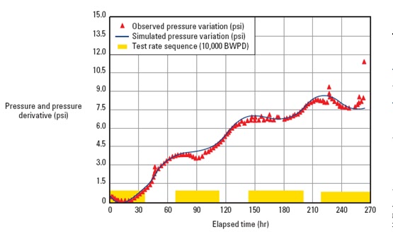
The following example illustrates how pulse testing was used to understand the degree of hydraulic communication within a Middle Eastern reservoir and to investigate suspected fluid migration toward a nearby field. The test involved six wells, including the active well. The pulses were created by an alternating sequence of injection and shut-in periods of 36 hr each. The resulting pressure pulses were monitored in the observation wells for 12 days. Downhole memory recorders were used to acquire the pressure data.
The observed pressure responses were analyzed with history-matching techniques. The analytical solution of the diffusivity equation for a homogeneous rectangular reservoir with mixed boundary conditions (i.e., both no flow and constant pressure) yielded an excellent match between the measured and simulated pressure responses (Fig. 55). Figure 56 shows the configuration of producing and injection wells within the area modeled in the study.
Test sequence and corresponding pressure response in the observation well
(Mahmoud et al., 1993).
Configuration of producing and injection wells for the example pulse test.
The test indicated good hydraulic communication within the area investigated. It was also possible to determine the interwell reservoir properties and geometry of the area. The good match of constant-pressure boundaries to the data implied that there was no leakage toward the neighboring field as previously suspected.
The small amplitude of the signal detected in two of the observation wells suggested the presence of free gas in the upper part of the structure. This result was confirmed by other sources of information and proved particularly useful to the operator in locating future water injection wells and optimizing reservoir management.
New Technology:
Increased sophistication in testing demands additional tools, creating the need for a complex sequence of distinguishable pressure pulses, or operating pressure ‘windows.’ The annular pressure has to supply not only a discrete signal to one of a number of tools, but also the power to operate it.
For example, opening a single shot reversing valve at the end of a test can typically require 2000 to 3000 psi above the hydrostatic pressure. This creates significantly higher pressures in the annulus and great care must be taken not to exceed the tubing collapse or casing burst pressures. There is thus a limit to the number of discrete annular pressure signals that can be safely employed to command and power downhole equipment. A recent development addresses this limitation by employing much lower annular pressure variations as command signals to the downhole tools. The signals are analyzed by the tool’s controller which uses electronics to control the downhole test valve and circulating valve. Batteries power the electronics, annular hydrostatic pressure supplies the energy to operate the valves. The system is called the “Intelligent Remote Implementation System” (IRIS).
Low intensity coded pulses of at least 250 psi are sent down the annulus using the rig mud pumps. The key recognition factor for the IRIS system’s pressure sensor is the shape of the pressure pulse.
A threshold pressure has to be achieved, sustained and bled off within specific time and pressure variation constraints. The duration that a plateau pressure is sustained distinguishes one command from another.
In the tool, a microprocessor reads the coded pressure pulses, compares them to pre-set operating instructions and opens or closes solenoid valves to direct hydraulic fluid from chambers at annular hydrostatic pressure into chambers at atmospheric pressure. This fluid movement is used to operate the tool’s valves, closing them with a high intensity force driven by the differential pressure rather than by just the force of a spring, as in conventional systems. In addition, the fact that clean hydraulic fluid, rather than mud, is operating the tools means that reliability is also enhanced.

Intelligent Remote Implementation System (IRIS).
Annular pressure pulses needed to control the IRIS dual valve in conjunction with either pressure or drop bar operated TCP guns.
Since the tool functions through electrohydraulics, its mechanical construction is simplified. The 20 ft. (6m) IRIS dual-valve replaces conventional fullbore test strings measuring up to 40 ft. (12 m).
Elimination of pressurised nitrogen chambers also enhances the safety aspects of the tool. The equipment is compatible with conventional pressure operated test equipment including TCP systems.


