Introduction
The design of an efficient, safe and economical completion system is dependent
upon the acquisition of accurate data and the selection of appropriate
components. Since the ultimate success of the completion system is dependent
on its successful installation, the installation procedures should also be given
some consideration.
Completion designs will vary significantly with the variation of the following
reservoir and location characteristics:
- Gross production rate
- Well pressure and depth
- Formation properties
- Fluid properties
- Well location
- Existing stock
Completion Equipment
Selection
As with all downhole components, data on completion components must include
full details of dimensions, profiles and connections. This is a basic requirement
of all downhole equipment, but is of special significance in completion design
and installation since many future well service activities will require throughtubing
access.
Basic Dimensional Data
- Length (depth)
- ID/OD (internal & external diameters)
- Thread type
Tubular Components
When completing a well, the proper selection of tubular components is possibly
one of the most important decisions. Tubular components come in a number of
different grades and diameters and several factors must be considered prior to
selection.
The higher formation pressures encountered in recent years requires tubing
and components have a greater yield strength. In addition, improved sealing
mechanisms at connections are also required. The types of connections
available have also increased. Those involved with completion design and
installation must understand the proper application of common tubing and
component types. Similarly, a good working knowledge of common seals and
connections is necessary.
Inspection Procedures
A critical part of any well completion operation is the inspection of components
prior to final assembly and installation. Completion specialists and supervisors
must be aware of necessary inspection procedures, as well as the basic handling
procedures for each completion component.
Tubing String
Specification
Specification
Tubing generally provides the primary conduit from the producing interval to
the wellhead production facilities. Therefore, the proper selection, design and
installation of tubing is a very important part of any completion system.

Tubing Length
Tubing joints vary in length from 18 to 35 feet although the average tubing
joint is approximately 30 feet. In any tubing shipment the joint length will vary,
so accurate measurement of each joint is essential. Pup joints (for spacing out
the string) are available in shorter lengths (2’ - 20’) in 2’ increments.
Tubing Diameter
Tubing is available in a range of OD sizes. The most common sizes are 23/8", 27/8",
31/2" and 41/2" (51/2", 7" and 95/8" tubing is fairly common in some areas e.g., the
North Sea). The API defines tubing as pipe from 1" to 41/2" OD. Larger
diameter tubulars being termed casing (41/2" to 20").
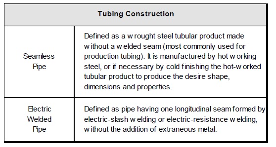
Tubing Construction
Most types of tubing joint are threaded on each end (pin end) and connected
by couplings (box). The pipe used for production tubing may be manufactured
by one of two methods
Tubing Classification
Criteria
Criteria
The following criteria are used to classify or specify tubing string material and
joint construction:

API Tubing Grades
Much of the tubing used is manufactured according to API specifications and
must undergo a wide variety of tests and checks before shipment and
installation.
Standard API steel grades for tubing are J-55, C-75, L-80, C-95, N-80, P-105 and
V-150. Grades C-75, L-80 and C-95 are intended for hydrogen sulfide service
where higher strength than J-55 is required.
NOTE: L-80 may be 4130/4140 LHT material, 9Cr LHT, or 13Cr material.
Color Bands
The grade of new tubing can be identified by color bands:

High Strength
Tubing
Tubing
High strength tubing is generally considered to include grades with a yield
strength above 80,000 psi. C-75, L-80 and N-80 are often included because
their as-manufactured yield strength often exceeds 80,000 psi. High strength
tubing, particularly P-105, presents an increased sensitivity to sharp notches
or cracks.
Any sharp-edged notch or crack in the surface of a material is a point of stress
concentration which tends to extend the crack progressively deeper into the
material, much like driving a wedge. Low strength materials are soft and ductile
and will yield plastically to relieve the stress concentration. High strength
materials do not yield to relieve the stress concentration and tend to fatigue or
fail more rapidly when subjected to cyclic stresses.
Maximum Allowable
Stress
Stress
Calculation of the maximum allowable stress of a certain pipe is carried out by
multiplying the minimum cross sectional area of the pipe, times the minimum
yield strength rating of the pipe